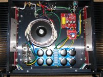
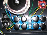
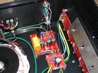
I don't remember any "official" schemo but up to 30-32V -V, NP has given the fearless amplifier builder the go-ahead. The top side (TAIL) of the diff pair uses a resistor to loose unecessary voltage...
Beyond that, 8-10V on the JFETs is a good number in my experience. BJT's are said to perform better as cascodes. You still need to bias the second stage appropriately...

Beyond that, 8-10V on the JFETs is a good number in my experience. BJT's are said to perform better as cascodes. You still need to bias the second stage appropriately...
I don't remember any "official" schemo but up to 30-32V -V, NP has given the fearless amplifier builder the go-ahead. The top side (TAIL) of the diff pair uses a resistor to loose unecessary voltage...
Beyond that, 8-10V on the JFETs is a good number in my experience. BJT's are said to perform better as cascodes. You still need to bias the second stage appropriately...

Dear flg
I have already 30 V rails and want to go up to 50 V in order to have more power.
Thanks
Nikosgar I will refer you the schematic I did and the amp I built see the following post in this thread. Post 279,416,417,420,449,453,454. See if this will get you started.
JimM
Dear JimM,
Thanks for pointing to the right direction.
I have seen your schematics and implementation (excellent & inspiring).
Questions
I have notice on your final schematic layout that for R203-R204 you are using different values (200 K & 150 K) why? (in your first schematics you had both on 200K).
According to the BA-2 manual those two are equal and are changing the gain (47.5K around 15db (initial setting by NP) - 100K /20db-150K /23db)
Can you post your PCB layout
Thanks for all the help and support
JimM sold a few boards to me which I used in BA2 running about 55v.
I would see if he can help you out. they work fine.
please !!!!! do !!!!!! that would be wonderful !!!!!! if you can
nikosgar I think the final value I ended up with in R203 and R204 was 97.7k in both places, the 200k and 150k was wrong, it should have been one or the other in both places. I choose the 97.7k value to match the output of my benchmark DAC. If you will send me a P.M. with email address I will respond, and yes I do have som boards left.
JimM
JimM
nikosgar I think the final value I ended up with in R203 and R204 was 97.7k in both places, the 200k and 150k was wrong, it should have been one or the other in both places. I choose the 97.7k value to match the output of my benchmark DAC. If you will send me a P.M. with email address I will respond, and yes I do have som boards left.
JimM
Dear JimM
You got mail
Joes Ba2 please help
OK I am a green horn when it comes to building amps, I can read schematics but I need to know when mr pass says standard relating to capacitors or resistors as far as voltage wattage etc. is concerned what is standard? I can see in the schematics it calls for a 1000 uf cap but what is the voltage also the resistors the big ones say 3 watts the others must be the standard thing lol, I have the ba2 boards, I need to be pointed to a decent case and power supply, some links would help, I would like to thank anyone who helps me out ahead of time.
OK I am a green horn when it comes to building amps, I can read schematics but I need to know when mr pass says standard relating to capacitors or resistors as far as voltage wattage etc. is concerned what is standard? I can see in the schematics it calls for a 1000 uf cap but what is the voltage also the resistors the big ones say 3 watts the others must be the standard thing lol, I have the ba2 boards, I need to be pointed to a decent case and power supply, some links would help, I would like to thank anyone who helps me out ahead of time.
For those 3 watters many will use the Panasonic ERG series metal oxide film resistors, also commonly used as source resistors in the output stage. For the rest of those small resistors I like to use the Vishay/Dale CMF55 series (1/4 watt). Capacitor voltage rating should be higher than whatever rail voltage you are feeding the stage with. 24V rails as shown, 25V caps are OK. Case - look in the diyaudio store to see if something there could be an option for you. Transformer - jump in on that SumR group buy, but it's closing real soon so hurry.
depends on your railvoltage. eg. if rail=25v caps need to be >25v.
case is in the store in top of page.
power supply boards also in store.
transformer depends on witch part of the world you live in.... post is expensive, but in Europe maybe this?? : 58-0300-018-S TALEMA - Transformator: toroidformad | Transfer Multisort Elektronik
or bigger trafos in VA.
I belive there is some GB too. just search in the GB forum .
Stig
You won't have the correct bias boards if you want a BA-2. This is just me, but if I wanted 100W I guess I would build 2 F4's and run them "balanced mono". Read the F4 service manual at firstwatt.com to understand how to set them up as such (and drive requirements, etc.). People have scaled up the BA-2 but you really need to understand what you're doing if going that route. I think Teabag is one of those folks. Might be easier just to get more efficient speakers that work well with 20~30 watts.
problems with my BA-2 monoblock build
Wondering if anyone can steer me in direction to look for my problems.
I am building BA-2 monoblocks. 300va transformers 20-0-20v using Cviller PS boards, and am using the diyAudio circuit boards. Built up one monoblock, and did the powerup as recommended in the BA-2 article. I am using 2 output boards with 6 matched 240s and 6 matched 9240s. Easily able to get DC offset to 0mv on the gain board and outputs. Voltages all are very close to published values in the article for the gain board. Only parts substitutions are increasing the voltages on the caps to handle the 25 or 26vdc rail voltages I have.
I can easily bias the output transistors to around 250mv, with about 0.5Amp total current draw, with no input signal. Heat levels are about 15 degrees above ambient on the heatsinks.
My problem is that when I put a test signal (1 khz from a Leader signal generator) into the unit, I do not get any gain, perhaps a loss of 15% when checked at the output of the gain board, or at the speaker outs. Even worse is that as I increase the input signal voltage, I get an increase in the current draw of the unit, such that 1 volt input takes me from 0.5A to about 2.0A current draw.
Built up the other mono and it does the same thing!
I obviously must have some wiring wrong, but cannot understand where or how….
Any suggestions on what I screwed up?
Thanks, Matt
Last edited:
- Home
- Amplifiers
- Pass Labs
- Burning Amplifier BA-2


