Are you suggesting a 10uF cap sounds the same as any other 10uF cap?
What I can say is that my RC network sounds different if I turn it around. Of course it could be a change in contacts due to movement, or my ears of course or my emotions, psychological influences etc. Oh and that of course.
But in the end I must trust my ears over physics.
What I can say is that my RC network sounds different if I turn it around. Of course it could be a change in contacts due to movement, or my ears of course or my emotions, psychological influences etc.
Oh and that of course. But in the end I must trust my ears over physics.
Yes,RC chain is R and C series connected - between two nodes ;
it's irrelevant is it RC or CR
a series RC is the same as a series CR.
If you can hear a change, then you are changing something else.
I am probably reaching the end point of upgrading the BA-2 front end with a voltage regulator. I have used the Salas reg with good results resulting in a reduction in background noise and image clarity and detail. However, the sound of the BA-2 being run from Nelson's power supply was also very good to start with having a warm depth to the soundstage and images alike with plenty of good dynamics so it was going to take a lot to keep this and make improvements. The regulator certainly had gone some way towards this by improving those aspects already mentioned but that warmth and something of the soundstage and musical image depth had been lost. So I have replaced the Panasonic TS-HA 10,000 caps with Mundort 4700uF on the regulator and the overall sound has lost its somewhat flattened perspective in favour of the pre-regulator soundstage depth as well as sound image depth. To my ears the music is now flowing better and the muscial timbres are more natural.
Hope this helps for those wondering about components.
Chris
Hope this helps for those wondering about components.
Chris
what is the power out put of BA-2 ?
I don't know and it probably depends on how many power boards per channel are used. All I can say is that using one power board per channel is enough to drive my Dynaudio Contour 1.8MkII loudspeakers at a loud level for me with the pre-amp volume turned half way round.
what is the power out put of BA-2 ?
it's set by your rail voltage, I think the expression is approximately 1/2*(Vrail^2)/Rspeaker
So, 25 V rails, 8 ohm speakers, you get nearly 40 W. It won't be class-A here though, 25 V and class-A through 8 ohm speakers would need 3 A of idle current.
BA-2 ground loop issue
I experience a major ground loop issue after inter-connecting the amp input with the pre amp out puts.
When i connect only one of the in amp channels with the pre amp out everything is normal no any hum or any other kind of noise and when i connect the other input as well all hell breaks loose (loud hum and noise altogether).
I am only operating the amp using single-ended (RCA) input and according to BA-2 manual i have shorted the negative input (IN-) to ground on the front end pcb.
Only one ground of the front end is returned to the main star ground.
The front end itself is been supplied by a separate power supply (shunt regulator) with its common (0) been connected to the main star.
From that main star ground i connect to the chassis thru diode bridge and then to AC earth.
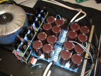
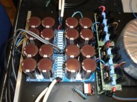
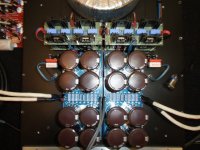
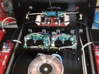
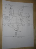
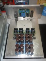
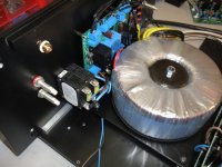
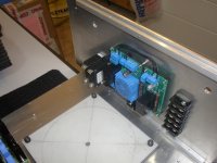
Below you can see my pcb wiring connection diagram and some photos .
Please help!!!!!
I experience a major ground loop issue after inter-connecting the amp input with the pre amp out puts.
When i connect only one of the in amp channels with the pre amp out everything is normal no any hum or any other kind of noise and when i connect the other input as well all hell breaks loose (loud hum and noise altogether).
I am only operating the amp using single-ended (RCA) input and according to BA-2 manual i have shorted the negative input (IN-) to ground on the front end pcb.
Only one ground of the front end is returned to the main star ground.
The front end itself is been supplied by a separate power supply (shunt regulator) with its common (0) been connected to the main star.
From that main star ground i connect to the chassis thru diode bridge and then to AC earth.
Below you can see my pcb wiring connection diagram and some photos .
Please help!!!!!
Attachments
On my ba2 boards the front end ground's are separate, so if you only have one side of the front end board grounded then the other side is not tied to ground you need to tie both front end grounds to the common ground point. If I understand what you have written i.e. Only one ground of the front end is returned to the main star ground.
Check the F5 thread, someone had a similar problem. Also make sure that the RCA connectors are isolated from the chassis.
On my ba2 boards the front end ground's are separate, so if you only have one side of the front end board grounded then the other side is not tied to ground you need to tie both front end grounds to the common ground point. If I understand what you have written i.e. Only one ground of the front end is returned to the main star ground.
Dear JimM
It is a dual mono configuration with separate power supply's one unregulated for the output stage and one regulated for the front end the only common thing that the two channels are charring is the transformers one for the output and one for the front end.
That means that i have actually two common star grounds.
One on itch channel capacitor philter pcb all gnd's per channel are returning to its own assigned common gnd (0) point (one gnd from the front end & one from its power supply).
The RCA inputs are isolated from the chassis.
Can someone advise on ground wiring on this setup !!!!
Check the F5 thread, someone had a similar problem. Also make sure that the RCA connectors are isolated from the chassis.
Dear ENSen
The RCA input connectors are isolated from the chassis.
Thanks
Dear JimM
It is a dual mono configuration with separate power supply's one unregulated for the output stage and one regulated for the front end the only common thing that the two channels are charring is the transformers one for the output and one for the front end.
!!!![/U]
There is probably a difference in resistance between your two star grounds and I don't see the reason for two separate connections here (I may be wrong here so see what the others say on this issue).
Also you may have some resistance issues if you are connecting the star ground to the chassis earth via two separate diode arrangements.
I would establish a single common star ground for both channels, don't use two separate ones.
This single star ground for both channels can be connected to the chassis then via a CL60 thermistor just to simplify matters. If that works and you want to put back the diode arrangement then go ahead and try it.
Also, have you carefully checked all your voltage regulators and do their grounds link to each star ground?
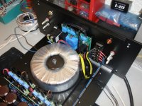
From looking at your pictures and what you have said it appears you have one common transformer feeding both regulators and power supplies. I would think you need to have a common ground for both sides or have seperate transformers per side. I would trouble shoot the problem starting with a good ohm meter and check for continuity from centeral ground (star ground, signal ground) to points on pc boards and power supplies.
Then check to see if chassis ground is tied to signal ground. I think if you will tie all star grounds and power supply grounds to one point you will fix your problem. Also what is your regulated voltage and unregulated voltages? Very impressive lay out send more pictures also how is your ac in wired to xformer.
Then check to see if chassis ground is tied to signal ground. I think if you will tie all star grounds and power supply grounds to one point you will fix your problem. Also what is your regulated voltage and unregulated voltages? Very impressive lay out send more pictures also how is your ac in wired to xformer.
From looking at your pictures and what you have said it appears you have one common transformer feeding both regulators and power supplies. I would think you need to have a common ground for both sides or have seperate transformers per side. I would trouble shoot the problem starting with a good ohm meter and check for continuity from centeral ground (star ground, signal ground) to points on pc boards and power supplies.
Then check to see if chassis ground is tied to signal ground. I think if you will tie all star grounds and power supply grounds to one point you will fix your problem. Also what is your regulated voltage and unregulated voltages? Very impressive lay out send more pictures also how is your ac in wired to xformer.
Dear JimM thanks for your advise
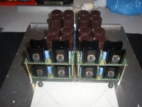
You can see a detail layout of the wiring and some constraction photos.
One thing that i have notice also is that the transformer of the unregulated supply is bazing excessively and this mechanical noise is audible thru the speakers.
p/s
Regulated voltage +/-25VDC (200mA) per channel for Front End.
Unregulated for the output stage is +/-22,7VDC (2,7Amp) per channel.
Attachments
I think I would tie all signal grounds to one point including unregulated and regulated supplies together at one point, this should not hurt any thing if wired as shown on drawing. The other thing I would try and you may won't to do this first is bypass the soft start circuit.
One thing that i have notice also is that the transformer of the unregulated supply is bazing excessively and this mechanical noise is audible thru the speakers.
QUOTE]
What current and voltage is your transformer primary winding designed for? Buzzing can be caused by saturation i.e., transformer can't cope with the primary voltage.
Does it buzz when connected to the house power supply but with the secondaries unconnected?
- Home
- Amplifiers
- Pass Labs
- Burning Amplifier BA-2