Inspired by many people here and after reading an endless amount of posts in different AlephX threads I decided to brew something for my own.
And finally, here are the results:
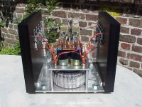
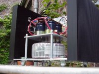
From the start the idea was to give the amp a solid and industrial look.
With the black anodised heatsinks and the alu this was not a very difficult task. However, I tried to use the ‘metal’ colours as much as possible. I cut off the plastic from the small caps on the driver board, and maybe in time I’ll dismantle the big caps in the PSU also. Just for the look. I’m not sure if I can hear difference in sound, if any.")
The cap-bank is placed on an alu plate, which is held in place with alu pipes and shiny bolts. The biggest nuts and bolts I could get at the local store were used for the feet.
The front and top have no cover, and I still can’t decide if I’ll ever make them. No children around, only the cat. Big problem for the blue LED.
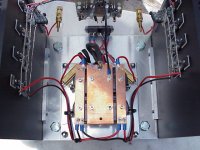
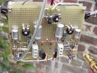
There are still some resistor values to play with as you can see on the point to point board.
That board is entirely made p-to-p, with the wires as much as possible on the backside.
Its’ quite small, 10 X 8 cm (3,94 X 3,15 inch) and carries all of the components except the power transistors and surrounding components. No fancy stuff was used in the whole amp.
Guess I would have to order the black gates at Jean-Paul’s and the Vishay-Dales at Peter Daniel’s)
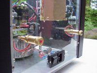
The output resistors (2 x 8 x 0.47ohm in parallel) are well tied together, and some people already asked me where the ignition is mounted.
I had (and still have) a problem with the power supply. The caps I bought are rated 25V. The power transformer is 22-0-22 and after the bridge and caps I get 28V under load. That’s why I had to mount two series resistors after the rectifier. They spoil a huge amount of heat and mounted together with the rectifier on the alu plate, it gets too hot.
Thanks to Grey and Nelson, Peter Daniel (inspired me the most with the mechanical building), and others, from which I learned a lot.
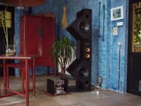
They will drive two B&W800Matrix, who are located in the huge living room of the old factory where we live. (Always liked old factories and industrial stuff).
/Hugo - Up to the bench for the making of BOAX… (Brother_Of_AlephX)
And finally, here are the results:
From the start the idea was to give the amp a solid and industrial look.
With the black anodised heatsinks and the alu this was not a very difficult task. However, I tried to use the ‘metal’ colours as much as possible. I cut off the plastic from the small caps on the driver board, and maybe in time I’ll dismantle the big caps in the PSU also. Just for the look. I’m not sure if I can hear difference in sound, if any.
The cap-bank is placed on an alu plate, which is held in place with alu pipes and shiny bolts. The biggest nuts and bolts I could get at the local store were used for the feet.
The front and top have no cover, and I still can’t decide if I’ll ever make them. No children around, only the cat. Big problem for the blue LED.
There are still some resistor values to play with as you can see on the point to point board.
That board is entirely made p-to-p, with the wires as much as possible on the backside.
Its’ quite small, 10 X 8 cm (3,94 X 3,15 inch) and carries all of the components except the power transistors and surrounding components. No fancy stuff was used in the whole amp.
Guess I would have to order the black gates at Jean-Paul’s and the Vishay-Dales at Peter Daniel’s)
The output resistors (2 x 8 x 0.47ohm in parallel) are well tied together, and some people already asked me where the ignition is mounted.
I had (and still have) a problem with the power supply. The caps I bought are rated 25V. The power transformer is 22-0-22 and after the bridge and caps I get 28V under load. That’s why I had to mount two series resistors after the rectifier. They spoil a huge amount of heat and mounted together with the rectifier on the alu plate, it gets too hot.
Thanks to Grey and Nelson, Peter Daniel (inspired me the most with the mechanical building), and others, from which I learned a lot.
They will drive two B&W800Matrix, who are located in the huge living room of the old factory where we live. (Always liked old factories and industrial stuff).
/Hugo - Up to the bench for the making of BOAX… (Brother_Of_AlephX)
Attachments
Thanks for posting! Excellent PtoP wiring.
I was wondering if those were B&W 800's! Very nice
setup : ) The 800's don't have to be bi-amped?
sorry to hear about your power supply problem. I guess the only
thing you can do in the end is get a new transformer...
thanks for sharing!
it's nice ot see some AX's start to show up.
moe29
I was wondering if those were B&W 800's! Very nice
setup : ) The 800's don't have to be bi-amped?
sorry to hear about your power supply problem. I guess the only
thing you can do in the end is get a new transformer...
thanks for sharing!
it's nice ot see some AX's start to show up.
moe29
Hugo,
looks very good. what was the story in the end with the measurements? Do you still hear the distortion? What do the rail end up to be after the resistors? What bias do they run? What mosfet did you use?
The only thing I would change is the placement of the voltage drop resistors from where they are to the base plate. That should increase the life span of the caps.
I new you would reply as first!!
Those B&W's can even be tri-wired, altough they play very good with a single wire. I bi-wired them till now.
Yes, that power supply...maybe I sell those transformers, and buy other ones. The trouble is that these ones are 1000VA and the 18-0-18 I can buy are only 750VA.
Or I change the caps. Or find something else. Still don't know.
/Hugo
Last edited:
VERRRY NICE!!!
They are far too near the wall on the side. You`ll get some early reflections which can spoil everything.
I understand that You might not have enough space for this but just for a try move them away from that wall - at least another half meter - more is better - I bet this will make a HUGE difference(towards positive).
Another thing I would change is placement of the speakers!originally posted by grataku
The only thing I would change is the placement of the voltage drop resistors from where they are to the base plate. That should increase the life span of the caps.
They are far too near the wall on the side. You`ll get some early reflections which can spoil everything.
I understand that You might not have enough space for this but just for a try move them away from that wall - at least another half meter - more is better - I bet this will make a HUGE difference(towards positive).
grataku said:Hugo,
looks very good. what was the story in the end with the measurements? Do you still hear the distortion? What do the rail end up to be after the resistors? What bias do they run? What mosfet did you use?
The only thing I would change is the placement of the voltage drop resistors from where they are to the base plate. That should increase the life span of the caps.
Thanks Grataku
I still think there is space for improvements, playing with resistors. The distortion is nothing more than plain clipping. I cranked up the bias to a total of 7.5A and that's HOT!!!
The 0.5ohm resistors drop about 3.7V. That's more than 27W.
I'll have to get rid of them one way or another.
I'll definitely place them on the base plate later on, because the cap plate also cools the rectifier.
I now have +/-21 rail voltage.
A small calculation tells me that 21+3.7=24.7V. Safe enough for the caps, but in reality, without the resistors I end up with 28V no matter how high I set the bias. With the lowest possible bias the voltage climbs to 32V!
The mosfets are IRF9210 for the diff-pair, and IRFP240 for the power transistors. All others are BC550C. The current source is made with the TL431CLP.
Peter, that’s a good idea. We’ll see. The rigidity is surprisingly good for the moment. The whole amp is bolt together only with 24 M4 screws.
BTW, how could I possibly inspire you???

/Hugo
Re: VERRRY NICE!!!
They can be ordered in any amount.
Part of the 'industrial' look
/Hugo
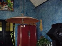
Thanks, I noticed that in the past. The living room where they stand is very nice (thanks to my wife) but is in no way good for sound. There is a high ceiling that ends in a ^-shape (don't know the name of those ceilings). Besides that there is a big lamp (1m diameter) hanging between the speakers which has a dramatic influence on the sound. And last but not least, there's the WAFcocolino said:
Another thing I would change is placement of the speakers!
Bricolo said:are those feets copyrighted? :d
I never thought about using this as feets, the easyest solution is ever the last that comes to my mind...
They can be ordered in any amount.
Part of the 'industrial' look
/Hugo
Attachments
Netlist said:
Thanks Grataku
I still think there is space for improvements, playing with resistors. The distortion is nothing more than plain clipping. I cranked up the bias to a total of 7.5A and that's HOT!!!
The 0.5ohm resistors drop about 3.7V. That's more than 27W.
I was using the same scheme to lower the voltage of my bench PS: 50 W ohmite resistors bolted on a plate of about the same size as your current one. I did measure some crazy temperatures like 150 C. At turn on they where making some metal sizzling noise.

I'll have to get rid of them one way or another.
The easyest way out that I see, if you want to keep the transformers, is to go all out. Make each monoblock with 4 heatsinks and use the full voltage swing from the trafo, sell the caps and buy a new set with higher voltage. Basically, make it a fully fledged XA200.
Re: Re: VERRRY NICE!!!
OK, but before, to be sure they are good quality, I'll order you 4 free samples
Netlist said:
They can be ordered in any amount.
Part of the 'industrial' look
/Hugo
OK, but before, to be sure they are good quality, I'll order you 4 free samples
Re: Re: Re: VERRRY NICE!!!
They will be available soon, via Karen from PassDiy
She knows how to take care of people who ask for "free samples".
/Hugo
Bricolo said:
OK, but before, to be sure they are good quality, I'll order you 4 free samples
They will be available soon, via Karen from PassDiy
She knows how to take care of people who ask for "free samples".
/Hugo
Re: Re: Re: Re: VERRRY NICE!!!
Netlist said:
They will be available soon, via Karen from PassDiy
She knows how to take care of people who ask for "free samples".
/Hugo
Could you give me your bank account?grataku said:
The easyest way out that I see, if you want to keep the transformers, is to go all out. Make each monoblock with 4 heatsinks and use the full voltage swing from the trafo, sell the caps and buy a new set with higher voltage. Basically, make it a fully fledged XA200.

/Hugo
- Status
- This old topic is closed. If you want to reopen this topic, contact a moderator using the "Report Post" button.
- Home
- Amplifiers
- Pass Labs
- Industrial AlephX High Power version