I have seen a guy on YouTube use a solder wick role as a way of spreading solder to tiny legs. i think it helps with heat as well. Impressive!
Juma, I got my BF862's today. All I could do was laugh. Anybody who works with those little things regularly should be commended. Oh Yeah, I got 30, but i don't think that was enough.
You can get solder past from Kester -- I apply it with a really fine tweazer -- then you hold the part down with a probe and just touch the critter's legs with the soldering iron (I use a hako with a needle tip.)
If you have a lot to do you can adapt a toaster oven -- there's a specific protocol of heating and cooling that you're "supposed to follow".
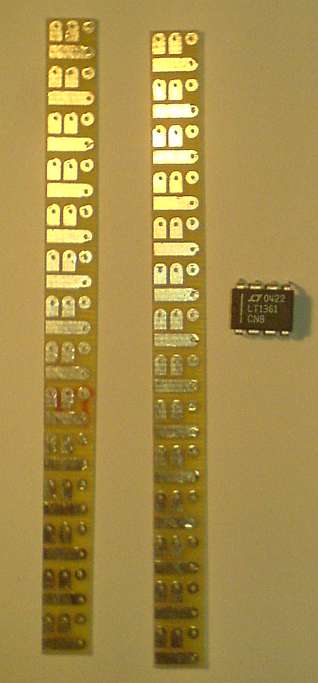
The RatShack protoboards have enough space between the traces to use "0805" components. For me, this allows a lot more components on a board.
Lastly, the gates of the paralleled BF862s will fit on the long runners, but not all smt transistors are configured the same.
I received a request for version of this preamp that uses 2sk170BL (Idss about 9mA). Right now k170 is easy to get and BF862 is a SMD component (not convenient for old hands and eyes), so here is the schematic.
The gain is a bit higher (9 dB) and the PSU is a bit different (be exact with input DC voltages +28V and -8V).
How much current needed for positive and negative supply?
how many times gain actually for 9db?
Sorry if my question to basic
Per channel :How much current needed for positive and negative supply?
Q1 and Q2 will draw Id near to Idss (at max. swing) from pos. rail
Q1 is alone on the neg. rail and it will draw a bit less (source doesn't swing as hard as drain) but let us allow for Idss too.
For stereo multiply that by 2 and allow enough margin for loses in PSU (shunt reg eats a lot of current).
Then multiply everything by 2 to be in comfortable zone..
Page 4 : http://www.live-audio.com/studyhall/dB_calculations.pdfhow many times gain actually for 9db?
Last edited:
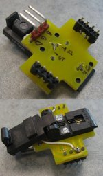
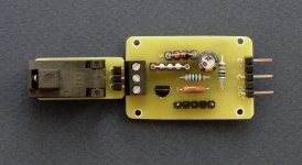
I finally got around to hacking a BF862 adapter together for my jfet sorting jig, using a 6-pin SOT-23 clamshell-type ZIF socket available reasonably cheaply on E-Pay. I had to do some rewiring, but I now have a jig that plugs into the "J170" socket on my tester, so I won't go insane trying to sort parts. I've had a strip of 100 parts waitng around for this development. I wont be doing this preamp, but instead have an RIAA amp that will use gain blocks consisting of a BF862 and a p-channel small signal mosfet. I'll be starting another thread for that project whaen I'm more sure of results.
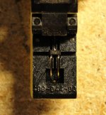
Anyway, if you search on E-Pay for "SOT-23", you'll run across a lot of parts, and several Chinese/HK sellers offering the socket. It's originally intended as an adapter for some PIC-type device in a 6-pin SOT-23 package, but it will accomodate a 3-pin SOT-23 just fine.
Anyway, if you search on E-Pay for "SOT-23", you'll run across a lot of parts, and several Chinese/HK sellers offering the socket. It's originally intended as an adapter for some PIC-type device in a 6-pin SOT-23 package, but it will accomodate a 3-pin SOT-23 just fine.
Attachments
That looks like the one from emcs2009 for $50 - SOT23-6 to DIP 8 PIC -
looks like the clamp presses the transistor down into a recess with the 6 (?) contacts underneath, yes? and connect the pins to external cctry for testing as per your photos.
Are there some extra transistor on the pcb? If I may ask, what do you use them for?
looks like the clamp presses the transistor down into a recess with the 6 (?) contacts underneath, yes? and connect the pins to external cctry for testing as per your photos.
Are there some extra transistor on the pcb? If I may ask, what do you use them for?
There's nothing extra on the PC board, though there are a few spots here and there for surface mount components. I added a 1k 805 resitor on the board (not visible) as a gate stopper, as the BF862 is very slippery. I've had problems with spurious readings in test jigs before due to oscillation with far less slippery devices - all my new test/sorting jig designs incorporate gate stoppers.
Just for clarification, a fair number of the wires you see labelled in the top pic are the gold-plated contacts coming from the socket - I labelled the ones I wanted to use and traced out where the PC board connections went with a VOM (I'm old, but I ain't stupid...). The red-based right angle header was added by me, and that's the bit that plugs into my jig. I cut traces and added jumpers to connect the chosen contacts in the socket to that header. I also removed a second PC board that was sandwiched on top of the one you see in the pictures using a hot-air pencil (a great tool for removing parts in plated-through holes where a fair number of pins are involved - the dragon's breath does it...). The header went into some of the holes left behind by that removal.
Last edited:
The Farnell socket looks like it's a better quality - at times, you do more or less get what you pay for. Instead of removing contacts (a direct solution - I still may do that), I marked the socket with white splotches indicating orientation). I may still amputate contacts... Chop, chop (think first, chop later...)
Last edited:
Resistor on output
Hi everyone,
I've spent a little time this afternoon fiddling with one of my versions of this preamp, and I found something I don't understand. (Again....)
Referring to the schematic in post #28, C4 (with C10, C11) and R9 (with the input impedance of whatever it's connected to taken into account, I guess) form a high-pass filter, blocking any DC. (Right?)
But what is R20's role? Is it a "safety resistor", as NP referred to something similar in his B1 article? And if so, how do you decide on its value? I notice that Juma changed the original 33R to 15R in the 2SK170 version in post #283, but why?
Apart from just wanting to understand, I would like to switch R20 for something a bit better quality I have kicking around, and am wondering what replacing the 33R with 56R would change (except for some loss of volume, I presume). I should add that I am not using C10/C11, and have a 10uF polypropylene in place of C4. I could just try it and see, of course, but I like to understand things when possible.
Regards
Nigel
...what is R20's role? ....
R20 is there to isolate the input capacitance of the next stage (including interconnects). We don't want to load the preamp with pure capacitance...
Last edited:
Hi Juma,
OK, I can see part of that - R20 would form a low-pass filter with the input capacitance (say Cin), and hence the value of R20 (say R)$ would determine the frequency of the filter - but I don't see how that would determine the value, since the input capacitance is surely pretty low, and hence the frequency (1/2(pi)R*Cin) is certainly high enough not for audio, isn't it?
Is 33R just a sensible balance between "not loading with pure capacitance" and not losing too much gain? If so then 56 R should work just fine, right?
Regards
Nigel
R20 is there to isolate the input capacitance of the next stage (including interconnects). We don't want to load the preamp with pure capacitance...
OK, I can see part of that - R20 would form a low-pass filter with the input capacitance (say Cin), and hence the value of R20 (say R)$ would determine the frequency of the filter - but I don't see how that would determine the value, since the input capacitance is surely pretty low, and hence the frequency (1/2(pi)R*Cin) is certainly high enough not for audio, isn't it?
Is 33R just a sensible balance between "not loading with pure capacitance" and not losing too much gain? If so then 56 R should work just fine, right?
Regards
Nigel
Hi ZM,
Unfortunately I only have two of them - they were left over from another project. Not a problem - I was hoping to fire up my soldering iron and tweak the preamp a little this evening, but I can always put a couple of 33R on my next parts order and do it some other time.
Ah, the point being that the low pass filter deals with the "ultrasonics", and has nothing to do with the audio band, as I (incorrectly) thought above...
Thanks ZM, and Juma, for the help.
Regards
Nigel
two 56R in parallel are even better

Unfortunately I only have two of them - they were left over from another project. Not a problem - I was hoping to fire up my soldering iron and tweak the preamp a little this evening, but I can always put a couple of 33R on my next parts order and do it some other time.
just take it as counter measure for ultrasonic oscillations , and (inter)connecting procedure safety
Ah, the point being that the low pass filter deals with the "ultrasonics", and has nothing to do with the audio band, as I (incorrectly) thought above...
don't go above 33R - it directly adds to preamp output impedance
Thanks ZM, and Juma, for the help.
Regards
Nigel
well - put there anything from 10 to 47 Ohms
whatever you have in drawer
I'm searching through the drawer as we speak... Trouble is that I usually use cheap no-name resistors I can get locally - for learning and having fun they're fine (and the 33R that are in the preamp now work just fine), but I suspect for critical points like this it would sound a little better to use something of more reliable quality. (Although I'm not a great believer in boutique parts...) The 56R I found are PRP but, as you say, too large a value.
Regards
Nigel
it depends ;
if next stage ( amp ) isn't current hungry ( low input impedance and/or capacitance ) , everything up to 100R is OK
maybe best thing for test is to put shortie instead ; that's best resistor - isn't it ?
but - I'm not expecting that you are going to hear too much difference
if next stage ( amp ) isn't current hungry ( low input impedance and/or capacitance ) , everything up to 100R is OK
maybe best thing for test is to put shortie instead ; that's best resistor - isn't it
?but - I'm not expecting that you are going to hear too much difference
- Home
- Amplifiers
- Pass Labs
- BF862 Preamp