Hello,
I recently bought a pair of Threshold S/1000 Series II modified to SA/1 (basically unbridged and gone to massive parallel setup). I already repaired with help from NP one of them that kept blowing railfuses by swapping a bad powertransistor. I tried to tune the biassetting with the 'Standard Amplifier Bias Procedure' from the Threshold Corp. (Feb 1991) but succeeded with only one of them. I can't get it stable at 42 degrees Celcius for the non-optical versions endtemperature because the VBE circuit keeps reacting much to violently when I turn the 5K multiturn biastrimmer.
What happens is that when I almost got i there after a few hours and I switch of the amp and turn it on next day the AC intake goes up to 2.5 A and stays there and the amp heats up far over 50 degrees Celcius. The other one is stable after 2 hours at 1.2 A AC and 43 degrees right on spec.
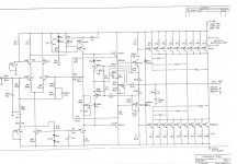
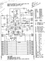
I'm planning to substitude the biastransistor but I've seen two Schematics from Australian user GeorgeHifi I believe but I can't determine which one is the latest (all non-optical bias).
One has a date on it that says November 1984, the other one has no visible date on it.
The one without a date has a transistor MPS6571 that is connected with the biastrimmer, the other schematic is too complex for me to be honest (I'm not a technician) and I don't no where to look for the problem.
I've seen the first series II S/1000 with a serial starting with B831000091 impliying October 1983 or week 10 1983. Mines are B84030030 & B84010011.
I can't see the parts on the Audioboard very well because it's attached to one of the mainboards with the powertransistors and the components on it are faced to that mainboard. I have to desolder first but I can't make any measurements at a live circuit with Coldspray that helped me onec with a bad driver and a biasproblem with a Levinson ML-3.
So which is the Series II schematic and what could be the problem.
Thanks in advance!
I recently bought a pair of Threshold S/1000 Series II modified to SA/1 (basically unbridged and gone to massive parallel setup). I already repaired with help from NP one of them that kept blowing railfuses by swapping a bad powertransistor. I tried to tune the biassetting with the 'Standard Amplifier Bias Procedure' from the Threshold Corp. (Feb 1991) but succeeded with only one of them. I can't get it stable at 42 degrees Celcius for the non-optical versions endtemperature because the VBE circuit keeps reacting much to violently when I turn the 5K multiturn biastrimmer.
What happens is that when I almost got i there after a few hours and I switch of the amp and turn it on next day the AC intake goes up to 2.5 A and stays there and the amp heats up far over 50 degrees Celcius. The other one is stable after 2 hours at 1.2 A AC and 43 degrees right on spec.
I'm planning to substitude the biastransistor but I've seen two Schematics from Australian user GeorgeHifi I believe but I can't determine which one is the latest (all non-optical bias).
One has a date on it that says November 1984, the other one has no visible date on it.
The one without a date has a transistor MPS6571 that is connected with the biastrimmer, the other schematic is too complex for me to be honest (I'm not a technician) and I don't no where to look for the problem.
I've seen the first series II S/1000 with a serial starting with B831000091 impliying October 1983 or week 10 1983. Mines are B84030030 & B84010011.
I can't see the parts on the Audioboard very well because it's attached to one of the mainboards with the powertransistors and the components on it are faced to that mainboard. I have to desolder first but I can't make any measurements at a live circuit with Coldspray that helped me onec with a bad driver and a biasproblem with a Levinson ML-3.
So which is the Series II schematic and what could be the problem.
Thanks in advance!
Attachments
Thanks
You mean the N-Channel JFets Q1 & Q2 I pressume?
What would be the likely offender?
The .15 uF Tantalum C5 or one of the four transistors that are connected with it like the MPSA92 (Q10) or MPSA42 (Q15) or the driverpair MPSU10 & MPSU60 (Q18 & Q17).
The question is: the behaviour of which transistor is directly modified by the biastrimmer P1?
It seems to me that the feature that seems to take care of a shorter startup sequence to reach the right operational temperature quicker is not working properly. I tested the bluebubbled Thermistors T1 & T2 with Coldspray and a blower and they seem to work just fine.
Heat lowers the biascurrent Cold rises it as expected.
Retrofitting the optical biasboards would certainly help here")
You mean the N-Channel JFets Q1 & Q2 I pressume?
What would be the likely offender?
The .15 uF Tantalum C5 or one of the four transistors that are connected with it like the MPSA92 (Q10) or MPSA42 (Q15) or the driverpair MPSU10 & MPSU60 (Q18 & Q17).
The question is: the behaviour of which transistor is directly modified by the biastrimmer P1?
It seems to me that the feature that seems to take care of a shorter startup sequence to reach the right operational temperature quicker is not working properly. I tested the bluebubbled Thermistors T1 & T2 with Coldspray and a blower and they seem to work just fine.
Heat lowers the biascurrent Cold rises it as expected.
Retrofitting the optical biasboards would certainly help here
I already did that. Substituded the 5K one-turn Bourns for a 20-turn Spectrol. The amp that has the "ideal" behaviour starts with 2.5 Amps AC within a minute, heats up to 45 degrees and then slowly tapers off to 1.3 Amps AC and settles within the hour for 43 degrees Celcius. If I let the other amp start with that value it maintains that 2.5 Amps AC and heats up considerably more and I can see that when the amp gets over 52 degrees Celcius the Thermistors kick in to hold back like the have a fight with a transistor that wants to supply more current. If I lower the amount of bias at the startup much more the the "ideal" amp this amp slowly creeps up to 1.6 Amps AC within let say an hour - so heating up much slowly then it should be - and then today reaching 42 degrees after 6 hours or so. But it can be different tomorrow. So the trick built in these amps to get more quickly to the ideal (musicplaying) temperature works with the one that is on spec but fails with the other one.
I'm feeling a bit like a racedriver (not being a mechanic) telling the engineer what seems to be wrong with his engine. I can describe the problem in a cognitive manner but fail to make a technical analysis cause lacking the technical skills.
I know Grey who has two S/500's substituted the .15 uF Tantalum that gave stability problems with one of them I believe with a Filmcap.
According to the 'Standard Amplifier Bias Procedure' from the Threshold Corp. (Feb 1991) all the opticalbias Stasis amps should be biased to 49 degrees Celcius and the non optical versions to 42 degrees. Was the biastracking/drifting always a concern for Threshold amps before the optical feedback implementation?
- Status
- This old topic is closed. If you want to reopen this topic, contact a moderator using the "Report Post" button.
- Home
- Amplifiers
- Pass Labs
- Schematics Threshold Series I or II