First Watt Aleph J input impedance
Hi Bob,
I noticed that Nelson Pass must of used R1+R2 as the input impedance because it is stated being 242Kohms in the manual for the First Watt
Aleph J. R1+R2 would be for our Aleph J-X 243.1Kohms which would be consistant with First Watt(s) Aleph J input impedance, so I ordered the components based on an ballanced input impedance for each positive & negative inputs of 243.1Kohms, for a 100Hz 12db per octive highpass Passive Line-Level Crossover(PLLC), I believe R1+R2 was explained in the A75 Power Amplifier documentation, have I made an error with respect to this ? In the end I will find out which is correct when the amplifier is tested upon completion, or should I recalculate the PLLC components values with a different input impedance before I assemble it ?
Thank You for your continued help
Scatterbrain001
Choky showed us that the input impedance is R1 (unbalanced by grounding the negative input) http://www.diyaudio.com/forums/pass-labs/145387-aleph-j-x-amp-project-48.html#post2301934
Balanced input impedance is 2xR1, since the negative input impedance is also R1. For balanced input, make two filters based on input impedance = R1.
Hi Bob,
I noticed that Nelson Pass must of used R1+R2 as the input impedance because it is stated being 242Kohms in the manual for the First Watt
Aleph J. R1+R2 would be for our Aleph J-X 243.1Kohms which would be consistant with First Watt(s) Aleph J input impedance, so I ordered the components based on an ballanced input impedance for each positive & negative inputs of 243.1Kohms, for a 100Hz 12db per octive highpass Passive Line-Level Crossover(PLLC), I believe R1+R2 was explained in the A75 Power Amplifier documentation, have I made an error with respect to this ? In the end I will find out which is correct when the amplifier is tested upon completion, or should I recalculate the PLLC components values with a different input impedance before I assemble it ?
Thank You for your continued help
Scatterbrain001
Power Supply DC Filter
Hi Everyone,
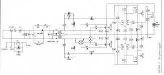
I have a problem in that I know nothing about DC filters, aside from the ten electrolytic 6800micro Ferrids capacitors with one 0.15microFerrids Film capacitor placed just before one of the AC lines into the Power Transformer(see Power Switch schematic below, I have discribed what is supposed to be in the green box labled DC Filter, I dont have an image of this on my computer, just a hard copy of it and I dont have a scanner), some how this dose not seem like a good solution, is it ? I wouldnt know ? I found another one on the internet is it better, it is made up of two electrlytic capacitors mounted with the negitive inputs linking the two capacitors with the positive terminals each linked to one of the AC inputs on the power transformer, and also some diodes (see schematic below).
Thank You for your help.
Hi Everyone,
I have a problem in that I know nothing about DC filters, aside from the ten electrolytic 6800micro Ferrids capacitors with one 0.15microFerrids Film capacitor placed just before one of the AC lines into the Power Transformer(see Power Switch schematic below, I have discribed what is supposed to be in the green box labled DC Filter, I dont have an image of this on my computer, just a hard copy of it and I dont have a scanner), some how this dose not seem like a good solution, is it ? I wouldnt know ? I found another one on the internet is it better, it is made up of two electrlytic capacitors mounted with the negitive inputs linking the two capacitors with the positive terminals each linked to one of the AC inputs on the power transformer, and also some diodes (see schematic below).
Thank You for your help.
Attachments
Hey all.
My apologies in advance for asking questions that may well be covered in this thread. At over 100 pages long it's a bit long to read the whole thing (whilst at work!) and I can't think of a good search term for what I'm looking for that won't turn up hundreds of answers.
To give some context, I've built a few amps and preamps, all from kits or PCB's purchased online, and in my wanderings around the internet I've found myself reading quite a bit around Pass amps. As such I thought I'd build one, and seeing as there are PCB's available for the Aleph J I thought I'd start there.
Having ordered the PCB's, I've started chasing parts.
So my question's are
1) 1SJ109 chips seem to be pretty rare. I've found a supplier of 1SJ109v chips at $10us a pop. Will these do? I'm ready to place an order but it makes sense to ask first...
2) What is the Aleph JX? Aleph J I understand (-ish), and have read a fair bit about, but -JX?
3)I've seen articles where folk have fed a balanced signal to a pair of amps with a view to reducing noise and increasing power. Can this be done with the Aleph J and what are the actual benefits? And where can I have a read about what/how to do that?
I guess that'll do for now, so 'thank you' in advance for anyone who takes the time to answer. Cheers!
Hi Bob,
I noticed that Nelson Pass must of used R1+R2 as the input impedance because it is stated being 242Kohms in the manual for the First Watt
Aleph J. R1+R2 would be for our Aleph J-X 243.1Kohms which would be consistant with First Watt(s) Aleph J input impedance, so I ordered the components based on an ballanced input impedance for each positive & negative inputs of 243.1Kohms, for a 100Hz 12db per octive highpass Passive Line-Level Crossover(PLLC), I believe R1+R2 was explained in the A75 Power Amplifier documentation, have I made an error with respect to this ? In the end I will find out which is correct when the amplifier is tested upon completion, or should I recalculate the PLLC components values with a different input impedance before I assemble it ?
Thank You for your continued help
Scatterbrain001
If you are building an Aleph J-X, then Zen Mod is correct.
I thought everyone had already agreed about that.
If you are building an Aleph J then it is a different story.
Hey all.
My apologies in advance for asking questions that may well be covered in this thread. At over 100 pages long it's a bit long to read the whole thing (whilst at work!) and I can't think of a good search term for what I'm looking for that won't turn up hundreds of answers.
To give some context, I've built a few amps and preamps, all from kits or PCB's purchased online, and in my wanderings around the internet I've found myself reading quite a bit around Pass amps. As such I thought I'd build one, and seeing as there are PCB's available for the Aleph J I thought I'd start there.
Having ordered the PCB's, I've started chasing parts.
So my question's are
1) 1SJ109 chips seem to be pretty rare. I've found a supplier of 1SJ109v chips at $10us a pop. Will these do? I'm ready to place an order but it makes sense to ask first...
2) What is the Aleph JX? Aleph J I understand (-ish), and have read a fair bit about, but -JX?
3)I've seen articles where folk have fed a balanced signal to a pair of amps with a view to reducing noise and increasing power. Can this be done with the Aleph J and what are the actual benefits? And where can I have a read about what/how to do that?
I guess that'll do for now, so 'thank you' in advance for anyone who takes the time to answer. Cheers!
1. You can get matched 2sj74s (p-channel jfets) from Blues and others on the forums. Be careful with buying 2sj109s off of Ebay and the like.
http://www.diyaudio.com/forums/swap-meet/161366-matched-toshiba-fets-sale.html
2. I've attached the Aleph J standard, single channel BOM written by another member. Again, this is a single channel BOM.
3. you can get the psu pcbs from briangt:
DIY Chip Amplifier Kits, PCB's, Components and Information. It's the pcb at the bottom of the page.
4. You can get Aleph J-X boards from Peter Daniels. Here is a link to the wiki
Group buy: Peter Daniels AJ-X pcb GroupBuy2 - diyAudio
He should still have boards. Here is a link to the BG thread created by him:
http://www.diyaudio.com/forums/group-buys/163900-aleph-j-x-pcb-group-buy-2nd-run.html
5. You should read through the entire Aleph j schematic and the thread you are currently reading: most of your questions will be answered by doing so
http://www.diyaudio.com/forums/pass-labs/111197-aleph-j-schematic.html
Cheers,
Greg
Attachments
Hi Bill
I tried with the (-) input grounded and not jumpering the C1. The the gate to source voltage is about 4V and the output to ground is very high. R7 is very low and R8 is normal.
I also measured the voltages with the Q1B removed (Q1A still in) and R7 and R8 become almost equal at 8.4 V. There was 8.4 volts between the source pin location and ground.
Thanks
Thank you!
Thank you for the reply's. Just being pointed at the right resources for me to read has resulted in a few lightbulb moments, so cheers for the assist folks!
I've already ordered the pcbs for psu and amps from Peter Daniels, so I'm looking forward to receiving those, and I'll get cracking with the components ASAP.
If anyone is keen to have a look, the link I found for the 2SJ109 chips is search 2SJ109 part, buy 2SJ109 at Utsource. I've not ordered as yet, but postage costs are quite high, so I'll probably go with the link provided earlier...
...and now on to the building and learning; thank you to you all for the help!
Hi Bill
I tried with the (-) input grounded and not jumpering the C1. The the gate to source voltage is about 4V and the output to ground is very high. R7 is very low and R8 is normal.
I also measured the voltages with the Q1B removed (Q1A still in) and R7 and R8 become almost equal at 8.4 V. There was 8.4 volts between the source pin location and ground.
Thanks
I'm assuming that the gate-source voltage you measured is at Q5-6. The gate-source voltage at Q7-8 is whatever is across R7. Q1b is stealing all the current, it's probably toasted, or some other possible but improbable miswiring is turning it all the way on. Time for a new pair, I would think.
i AM STILL CERTAIN THAT THE ballanced (+&-)INPUT IMPEDANCE IS 273.1Kohm
If this is correct definition, " the input impedance is the resistance the input see(s) through to ground " , then the Aleph J-X ballanced (+&-) input impedance is 273.1Kohms. I dont know why I am stuck here, I have ordered the components for all the posibilities I have herd here for the PLLC highpass xover.
What do you think, who is correct, I dont know?
If you are building an Aleph J-X, then Zen Mod is correct.
I thought everyone had already agreed about that.
If you are building an Aleph J then it is a different story.
If this is correct definition, " the input impedance is the resistance the input see(s) through to ground " , then the Aleph J-X ballanced (+&-) input impedance is 273.1Kohms. I dont know why I am stuck here, I have ordered the components for all the posibilities I have herd here for the PLLC highpass xover.
What do you think, who is correct, I dont know?
The difference is that each AJ-X input is also connected to an output through the feedback resistors. (a point I'd missed the first time until Zen Mod corrected me. What I originally said applies to non X/SUSY amps) This makes the jfet gates "virtual grounds", so the impedance a load sees is just the 22K input resistors.
For clarity: Zen Mod is right
For clarity: Zen Mod is right
Can anyone talk about a Power Supply DC Filter hypothesis
I have not herd from anyone yet discussing DC Filter theory, did I miss it ?Is it important to address a power supply DC Filter at all ?
Help ?
Hi Everyone,
I have a problem in that I know nothing about DC filters, aside from the ten electrolytic 6800micro Ferrids capacitors with one 0.15microFerrids Film capacitor placed just before one of the AC lines into the Power Transformer(see Power Switch schematic below, I have discribed what is supposed to be in the green box labled DC Filter, I dont have an image of this on my computer, just a hard copy of it and I dont have a scanner), some how this dose not seem like a good solution, is it ? I wouldnt know ? I found another one on the internet is it better, it is made up of two electrlytic capacitors mounted with the negitive inputs linking the two capacitors with the positive terminals each linked to one of the AC inputs on the power transformer, and also some diodes (see schematic below).
Thank You for your help.
I have not herd from anyone yet discussing DC Filter theory, did I miss it ?Is it important to address a power supply DC Filter at all ?
Help ?
Attachments

If you have significant DC or distortion on your mains it becomes very important to keep your transformers from mechanically buzzing. Many of us get along just fine without a DC filter. You might want to leave space in your chassis in case you need the filter and just try without it and see what happens.
The DC blocking for dummies version of the theory (at least as I understand it) is the diodes block a DC offset up to their forward conduction drop. That's why some of the circuits you posted earlier allow for multiple diodes, you may have more than .6VDC on your mains.
When the mains voltage swings above that drop, the diode conducts. When the main voltage swings back down below the diode drop, the diode stops conducting and the capacitor conducts the AC portion of the mains voltage until the voltage goes more negative and the other diode begins to conduct. repeat on the positive going part of the cycle.
Pretty simple really, the diodes block DC and the caps conduct enough to smooth out the waveform. If the load was perfectly resistive there wouldn't be a lot of current in the caps. It's not, and there is, so be sure that they are rated for a ripple current in excess of the line draw.
Edit: The A75 power supply you attached has no DC filtering. It has some RFI filtering for mains carried noise and that generated by the triac used for switching. RFI filtering is a good thing (the line rated caps across the mains, ad the MOV for spike protection). It also has an inrush limiter, TH1. Works fine leaving it in place although many would have you bypass it after the surge.
Last edited:
input impedance for passive filter
Hi Bob,
Thank you for the 22k input impedance because it makes sense to me, I will include with my next parts order to include components calculated for a 22Kohm input impedance for 100Hz for 12 db, or 120Hz for 6db.
The difference is that each AJ-X input is also connected to an output through the feedback resistors. (a point I'd missed the first time until Zen Mod corrected me. What I originally said applies to non X/SUSY amps) This makes the jfet gates "virtual grounds", so the impedance a load sees is just the 22K input resistors.
For clarity: Zen Mod is right
Hi Bob,
Thank you for the 22k input impedance because it makes sense to me, I will include with my next parts order to include components calculated for a 22Kohm input impedance for 100Hz for 12 db, or 120Hz for 6db.
DC filter & other power supply B4 transformer topics
Thank you for this detailed comment, I have a better understanding of it but have to read it a few times b4 I can research what you have told me.
How do I bypass the inrush limiter after the surge, a pysical switch ?
I have not ordered a Triac, is it importent, I know nothing about them ?
Thank You for your help, I will recieve the rest of my parts ordered after 06October2010 so I can then assemble my amplifier.
If you have significant DC or distortion on your mains it becomes very important to keep your transformers from mechanically buzzing. Many of us get along just fine without a DC filter. You might want to leave space in your chassis in case you need the filter and just try without it and see what happens.
The DC blocking for dummies version of the theory (at least as I understand it) is the diodes block a DC offset up to their forward conduction drop. That's why some of the circuits you posted earlier allow for multiple diodes, you may have more than .6VDC on your mains.
When the mains voltage swings above that drop, the diode conducts. When the main voltage swings back down below the diode drop, the diode stops conducting and the capacitor conducts the AC portion of the mains voltage until the voltage goes more negative and the other diode begins to conduct. repeat on the positive going part of the cycle.
Pretty simple really, the diodes block DC and the caps conduct enough to smooth out the waveform. If the load was perfectly resistive there wouldn't be a lot of current in the caps. It's not, and there is, so be sure that they are rated for a ripple current in excess of the line draw.
Edit: The A75 power supply you attached has no DC filtering. It has some RFI filtering for mains carried noise and that generated by the triac used for switching. RFI filtering is a good thing (the line rated caps across the mains, ad the MOV for spike protection). It also has an inrush limiter, TH1. Works fine leaving it in place although many would have you bypass it after the surge.
Thank you for this detailed comment, I have a better understanding of it but have to read it a few times b4 I can research what you have told me.
How do I bypass the inrush limiter after the surge, a pysical switch ?
I have not ordered a Triac, is it importent, I know nothing about them ?
Thank You for your help, I will recieve the rest of my parts ordered after 06October2010 so I can then assemble my amplifier.
Hi Bob, and others("et.al."-Latin for "and others")
I have recieved my soldering iron and filter fan, I purchased a BlackJack SolderWorks BK2000+ soldering station, and Cardas "TRI EUTECTIC ROLL SOLDER". I dont think it is working properly because I have to set the tempiture to 300degree celcius to just hardly melt the solder, which has a melting point of 220degree celcius. I have been practice soldering components on an F5 psu and have to have the iron set to 350degree to attach components to the board, but attached very poorly, 400degree celcius solder iron works well and creates good solder connections between the component and the board.
Is this normal, or do I have either a bad batch of solder, or need to recalabrate my soldering iron, to do this I will have to purchase some sort of thermometer which will probibly be expensive wast of money if the soldering iron is set properly from the factory.
Dose anyone have personal experiance that is consistant with the iron tempitures I have had to use, because many of my components say that I can use a 260degree celcius iron for ten seconds or the component will distroy due to my neglagance with soldering tempitures.
Thank You all for you continued responses, Very Many Thanks.
- Home
- Amplifiers
- Pass Labs
- Aleph J-X Amp Project