XJ Balanced connected.
+ Page
R11/R18 R12/R19 = 3.31Volt
R9/R16 R10/R17 = 3,89Volt
R16 - R19 = 0Volt
R7=3.4Volt
- Page
R11/R18 = 4,36 Volt
R12/R19 = 4,68Volt
R9/R16 R10/R17 = 4,19Volt
R16 - R19 = 0,52Volt
R7= 4,3Volt
Out +/- 16,2 Volt
Only - Page
- Page
R11/R18 = 3,26 Volt
R12/R19 = 3,48Volt
R9/R16 R10/R17 = 3,19Volt
R16 - R19 = 0,05Volt
R7= 2,21Volt
Out +/- 16,2 Volt
Last edited:

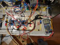
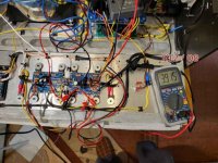
My aleph XJ is not working proberly.
RP = Euvl Version J74, capacitor + after Rp before P1, - ground.
Measuring points
R7 = 4,3V setpoint.
only + circuit board
R7= 4,6 V
only - circuit board
R7= 2,21V
sym. boards (+ and - board )
R7 + Boards = 3,4V
R7 - boards = 4,3V
Measuring points
P1 over R16 .
only + circuit board
R16 = 0,55V
only - circuit board
R16 = 0,05V
sym. boards (+ and - board )
R16 + board = 0,00V
R16 - board = 0,52V
Measuring points
R9 - R16 = 4,3V setpoint.
only + circuit board
R9 - R16 = 4,0V
only - circuit board
R9 - R16 = 3,89
sym. boards (+ and - board )
R9 - R16 + board 3,89V
R9 - R16 - board 4,19V
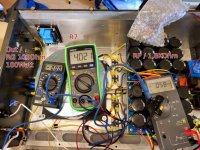
Out over RG (100R, 100W) max 50,0 mV DC
out only + board = 10,32V
out only - board = 0,00V
Out over + Board and – Board = 16,2 V
I hope the measurements are understandable.
My question, is 2SJ109 (Q1B) defective?
Pictures only with connected + board.
Lg Dirk
RP = Euvl Version J74, capacitor + after Rp before P1, - ground.
Measuring points
R7 = 4,3V setpoint.
only + circuit board
R7= 4,6 V
only - circuit board
R7= 2,21V
sym. boards (+ and - board )
R7 + Boards = 3,4V
R7 - boards = 4,3V
Measuring points
P1 over R16 .
only + circuit board
R16 = 0,55V
only - circuit board
R16 = 0,05V
sym. boards (+ and - board )
R16 + board = 0,00V
R16 - board = 0,52V
Measuring points
R9 - R16 = 4,3V setpoint.
only + circuit board
R9 - R16 = 4,0V
only - circuit board
R9 - R16 = 3,89
sym. boards (+ and - board )
R9 - R16 + board 3,89V
R9 - R16 - board 4,19V
Out over RG (100R, 100W) max 50,0 mV DC
out only + board = 10,32V
out only - board = 0,00V
Out over + Board and – Board = 16,2 V
I hope the measurements are understandable.
My question, is 2SJ109 (Q1B) defective?
Pictures only with connected + board.
Lg Dirk
Attachments

Last edited:
Hello Thanks for the help.
The amplifier sings.
But I still have a small problem.
If I have connected both channels via rca with a CD player, a slight hum comes out of the speakers in the break position.
If only the right or left channel is connected, the humming is not there.
The amplifier sings.
But I still have a small problem.
If I have connected both channels via rca with a CD player, a slight hum comes out of the speakers in the break position.
If only the right or left channel is connected, the humming is not there.
Did you short the XLR neg pin to ground pin on both channels?Hello Thanks for the help.
The amplifier sings.
But I still have a small problem.
If I have connected both channels via rca with a CD player, a slight hum comes out of the speakers in the break position.
If only the right or left channel is connected, the humming is not there.
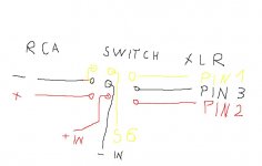
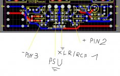
I have a switch for switching between XLR and RCA.
IN the RCA position is negative and mass is bridged.
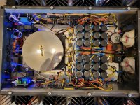
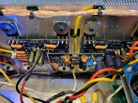
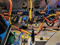
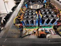
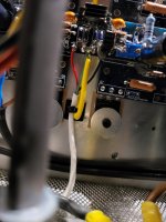
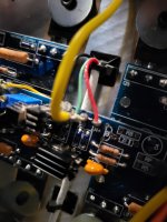
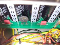
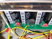
Could now only take pictures of the assembled amplifier.
I don't think this is very strong.
IN the RCA position is negative and mass is bridged.
Could now only take pictures of the assembled amplifier.
I don't think this is very strong.
Attachments

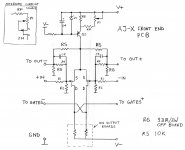
Sorry the bad drawing hopefully can recognize something.
Both inputs RCA short-circuited, no humming.
I found an error.
NTC on 1board, 2 pcb connected to metal abtan holders, NTC bridged.
( Only CD player (Euro plug) slight humming. CD and preamplifier (Schukostecker) very strong humming.)
Both inputs RCA short-circuited, no humming.
I found an error.
NTC on 1board, 2 pcb connected to metal abtan holders, NTC bridged.
( Only CD player (Euro plug) slight humming. CD and preamplifier (Schukostecker) very strong humming.)
Attachments

......
I found an error.
......
that means - no more hum, or it is still huming, with preamplifier connected?
now, you know that - when one apparatus in chain is connected to safety GND, you can lift other ones from safety GND, either in organized way ( option in apparatus itself) or with "cheater" plug - sometimes even simple isolating Schuko contacts on Schuko connector with sturdy isolation tape is good enough
Hello Pos.
1-4 after warming up and adjusting without load, preamplifier RCA and speakers connected.
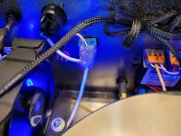
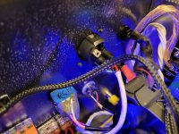
1. Upper board with capacitors insulated by plastic spacer, Strong hum.
2. Scam plug built, strong humming.
3. 100 ohm resistors installed in the ground line PSU, but no longer rest stable bais. Values are constantly changing.
4. CL 60 mass input removed from the board and placed directly on the star mass.
The amplifier starts to swim, no longer holds values and knocks loud 50 HZ.
With and without a scammer plug.
LG Dirk
1-4 after warming up and adjusting without load, preamplifier RCA and speakers connected.
1. Upper board with capacitors insulated by plastic spacer, Strong hum.
2. Scam plug built, strong humming.
3. 100 ohm resistors installed in the ground line PSU, but no longer rest stable bais. Values are constantly changing.
4. CL 60 mass input removed from the board and placed directly on the star mass.
The amplifier starts to swim, no longer holds values and knocks loud 50 HZ.
With and without a scammer plug.
LG Dirk
Attachments
Hello,
the JX sings wonderfully without humming, but the Bais values always change.
One day the values hold, the next day they change continuously.
I now want to build Peter's circuit using BJT, but I can't find a value for RP and P1.
After looking at the JX circuit, P1 / RP are parallel to R8 (1KOhm original J).
If I can take R8 2.2 KOhm, RP 1KOhm and P1 5KOhm, then I can regulate below and above 1KOhm R8.
Attachments
- Home
- Amplifiers
- Pass Labs
- Aleph J-X Amp Project