I have eperimented towards that goal  Please, would you share with us your approach(s) etc.
I've tried higher I, L loads in place of Aleph (not exactly ZV9 ) R loads in place of Aleph(ditto), dual cascoded JFETs, dual JFETs and one cascode MOSFET...
It has lead to some other (Off Thread ideas) but at this moment, for the initial "real" build, I have a B3(Peter D.) board stuffed w/some premo Vishay, Caddock, Holcro and elna/RelCap parts ??? ready to mount to more than enough Heat Sink and a 47V, 10A supply. I also have components for a 55V supply (probably the most promising improvement).
I just expected N.P. to give us a few Bread Crumbs of what he has in mind for the " more powerfull version" of That design???
I expect I will eventually use my ZV9/B3 amp on the top side of a Bi-Amped system driving my Ri Ribbon HF units. They are a little low in Impeadance/Resistance so that is most of the reason for eperimenting...

Please, would you share with us your approach(s) etc.I've tried higher I, L loads in place of Aleph (not exactly ZV9
) R loads in place of Aleph(ditto), dual cascoded JFETs, dual JFETs and one cascode MOSFET... It has lead to some other (Off Thread ideas) but at this moment, for the initial "real" build, I have a B3(Peter D.) board stuffed w/some premo Vishay, Caddock, Holcro and elna/RelCap parts ??? ready to mount to more than enough Heat Sink and a 47V, 10A supply. I also have components for a 55V supply (probably the most promising improvement).
I just expected N.P. to give us a few Bread Crumbs of what he has in mind for the " more powerfull version" of That design???
I expect I will eventually use my ZV9/B3 amp on the top side of a Bi-Amped system driving my Ri Ribbon HF units. They are a little low in Impeadance/Resistance so that is most of the reason for eperimenting...
flg said:I just expected N.P. to give us a few Bread Crumbs of what he has in mind for the " more powerfull version" of That design???
OK, here's a little crouton for you:
More Current and More Voltage.
Before the 4,8A version of Zen9 I built both Zen4 and Zen9 with “ordinary” quiescent current 2,8A, and was not quite satisfied with the bass from my Paradigm Studio 100 v4 loudspeakers. Exploring information about amplifier-loudspeaker interaction made clear that not only absolute value of speaker impedance Z, but also phase angle affect the peak current demand from power amp. That is, if the lowest Paradigm’s impedance is 3 Ohm at 80Hz, and the phase is not zero at this point, than the peak current consumption for 20V signal at 80Hz will be more than 7A. This is the first reason why I have tried 4,8A quiescent current. Second, achieving this current is easiest just with Zen9, since one must not trouble about driving of multi-transistor output stage.
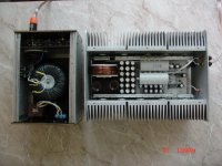
In order to feel myself safe with the elevated heat dissipation, I have employed 4 + 4 pcs of the laterals 2SK1058 (Q2 and Q3). Power supply voltage at the drain of Q4 (IRFP140N, schematics as in the Zen9 article by Nelson) is 54V, and 48V at the source of Q4. Q1 is LD1010DA unsoldered from the old computer motherboard. All transistors are mounted on ceramic pads (TO-3 form) that acts as electric insulators and quite good heat dissipators. Shottky diods also help to improve the bass, as well as 1 kW trafo (48v secondary) and LC-LC supply filter (0,5mH-50mF-1,5mH-60mF). Power supply is an external unit.
As of C1, I have used 35 pcs of Low-ESR Jamicon WG 680 microF x 63V, C2 and C6 are 30 microF Polypropylene capacitors.
Now I have tested and listened to one channel only (mono). Sound is the best of all my previous listenings. Hope to finish the second channel soon.
Attachments
Now I have the second external power supply ready for Zen9 4,8A monoblocks. I have connected them to my old Zen4 2,8A monoblocks, and was surprized a little bit with bass improvement from Zen4. Previous Zen4 power supplies contain 400W toroids and ordinary diods bridge (shunted with 0,1microF film capacitors). The Zen4 bass is still not as good as from Zen9 4,8A, but the difference is hardly distinguishable. It is hard to point out main reason, but, empirically, for 20-30W Zens and FirstWatt Fs power supply with 1kW toroid per channel and Shottky diods bridge can be recommended. Another plus from a big toproid is that it is completely silent at underloaded operation conditions.
I have also measured output impedances of both amps at 1 kHz. They are 0,9 Ohm and 1,4 Ohm for Zen9 and Zen4, respectively.
I have also measured output impedances of both amps at 1 kHz. They are 0,9 Ohm and 1,4 Ohm for Zen9 and Zen4, respectively.
Main assembling features of the Zen9 4,8A monoblocks – point-to-point soldering on 3mm PTFE board and multi-capacitor assembling of C1. All my efforts to achieve transparent sound with various 4700-22000 microF capacitors as C1 had no success (C7 shunt capacitor always 30 microF polypropylene). I hope somebody else will try and report his impressions from the multi-capacitor solution for C1 in Zen4 or Zen9 schematics. Even the wiring inductance of multi-capacitor assembling gives almost no negative effect as compared to drastic increase in sound transparency. Also one must especially care about C9 quality, since it sits in signal path.
Speaking about listening impressions one must also describe his complete system. My system components are:
Shanling CD-T1500 CD-player
Parasound JC2 Preamp
Zen9 or Zen 4 power amps
Paradigm Studio 100 v.4 speakers
Stereovox LSP-600c speaker cable (2m)
Nordost Blue Heaven interconnect cable (1,5m) XLR
Nordost Blue Heaven interconnect cable (1,5m) RCA
BlackNoise line filter
In this system I feel the speakers are a weak point, but system is OK to feel differences between various cables and other components.
You could try a biased bipolar for C1. 2 pair of 10,000uf 50v caps in seriese ( + -- + ) so you get a 100v 10,000uf bipolar cap then connect the center - terminal to ~ -20v through a high resistance. I have used a biased bipolar in another aplication where it realy made a big difference.
Interesting idea, but it requires additional supply rail. Did you try the proposed solution in a power amp? You are saying about big positive effect in another application, but, in many cases, when we feel sound improvement, we can not point out definite measurable parameter responsible for that improvement. Do you have any guess what could be a reason for the positive effect?
As for the multi-small-capacitor solution, I explained the positive effect by better relative mechanical rigidity of the internal structure of smaller electrolytic capacitors compared to big ones. Currents of the order of several amperes through a big electrolyte quite possibly can cause electro-mechanical effects that modulate and smear high frequencies.
As for the multi-small-capacitor solution, I explained the positive effect by better relative mechanical rigidity of the internal structure of smaller electrolytic capacitors compared to big ones. Currents of the order of several amperes through a big electrolyte quite possibly can cause electro-mechanical effects that modulate and smear high frequencies.
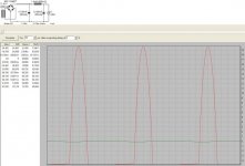
For schematics with elevated quiescent current, like for instance 4,8A, some cautions must be put to power supply design. Enclosed is a result of simulation of C1-L-C2 filter loaded by 4,8A constant current source. Other values are visible from the picture. Time dependences of currents through C1 and C2 are shown. Important is that RMS current through C1 consists 8,5A, while through C2 it is 0,1A only. So, one must care not only about the most important big C2 value, but possibilities of C1 as for acceptable ripple current must not be violated.
Attachments
Magura said:That's the right spirit...love you attitude!
Magura
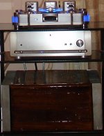
I see your point quite well. I did make a year ago a 50W version of Zen9 as stereo power amp. My god, sometimes I had to ask somebody to help me in moving it from listening place to working bench. It weight is close to 40 kg. You can see this monster in the enclosed picture.
Attachments
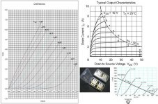
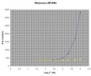
Below is a picture with measured output characteristics of LD1010DA transistor (i.e. dependences of drain current Id vs drain-to-source voltage Vds at various fixed gate-to-source voltages Vgs). It illustrates nicely the triode-like features of the device ingeniously apply in real schematics by Nelson Pass. The transistor was mounted on a heat sink during measurements. I hope this picture could be useful for DIYers who build Zen9 or F3.
I also have attached typical output characteristics of a pentode-like MOSFET (2SK1058) and of V-FET (or SIT) transistor TKS45F323. The last is really behave as a solid state tube. I would be very grateful if somebody knows where or from whom these TKS45F323 could be available.
I also have attached typical output characteristics of a pentode-like MOSFET (2SK1058) and of V-FET (or SIT) transistor TKS45F323. The last is really behave as a solid state tube. I would be very grateful if somebody knows where or from whom these TKS45F323 could be available.
Attachments
flg said:Great work Vladimirk
Now I need some time to digest...
I'm not familiar with the TKS45F323 or SIT? You don't mean SiC do you? I go search...
Vertical FETs or, in other words, Static Induction Transistors were discussed many times at this Forum, but the type indicated above is the best for audio among them.
Not the same, but similar transistors were used in the legendary Yamaha-B1 ana Yamaha-B2 amps.
Obtaining the TKS45F323 transistors would give big inspiration for every DIYer for a next project.
I have several of the Yamaha B-2's that I want to simplify
(zenify). Plan on using several stereo units and parallel the
2 channels per unit for more drive current for my Acoustat 2+2's.
(have 2 pairs of 2+2's and a pair of Model 2's.
Perhaps based on a Zen V5 (comp pairs). I guess the
2SK76 / 2SJ26 are depletion mode devices though
so designin new driver stage seems biggest hurdle.
On all but one unit that was modded to bypass the speaker
relay switches and input switch they are all noisy and
intermittent which is why I don't mind redesigning.
coloradosound said:I have several of the Yamaha B-2's that I want to simplify
(zenify). Plan on using several stereo units and parallel the
2 channels per unit for more drive current for my Acoustat 2+2's.
(have 2 pairs of 2+2's and a pair of Model 2's.
Perhaps based on a Zen V5 (comp pairs). I guess the
2SK76 / 2SJ26 are depletion mode devices though
so designin new driver stage seems biggest hurdle.
On all but one unit that was modded to bypass the speaker
relay switches and input switch they are all noisy and
intermittent which is why I don't mind redesigning.
Sure your intentions are absolutely correct. You first of all could think about removing or replacing old connectors and relays and even volume control. Speaking about the TKS45F323 transistors I have in mind a tube-spirit schematics with output transformer. But it will be off-topic to go into more detail here.
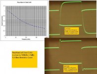
Speaking about the Damping Factor of power amp (this parameter is not so good with Zen or FirstWatt F amps) one should also remember about speaker cable. I’d like to show interesting measurements done with top-quality speaker cable STEREOVOX LSP-600c. Variations with frequency of absolute value of the cable impedance Z and of active component of this impedance are shown in the picture below. Next picture illustrates measurement setup used for these measurements.
One can see, that very well sounding cable measures terribly bad, its Z rises to several Ohms at 10-20 kHz ! It measures worse than a piece of cheap speaker wire. This story resembles situation with THD parameter.
One can see, that very well sounding cable measures terribly bad, its Z rises to several Ohms at 10-20 kHz ! It measures worse than a piece of cheap speaker wire. This story resembles situation with THD parameter.
Attachments

In the picture below I show the results of measurements
1) of Gain variation with Frequency (Pass Band measurements) and
2) of 10kHz Square Wave Response
for the Zen9 4,8A and Zen4 2,8A monoblocks. Load is 5,1 Ohm resistive.
Zen4 is approximately 10 times faster than Zen9 and indicates some problem with periodic set-up process, possibly its NFB compensation capacitor should be checked.
But what I would like to stress, listening of both amps (by me and several friends) do not reveal differences in highs reproduction, they are very subtle (if any), nobody can give preference to definite device. The bass and mids are better a little bit with Zen9.
At the same time, we immediately feel difference with highs, if we connect cheap speaker cable or replace output capacitor C1 (the replacement does not affect measurements).
The question is, again, to which level measurements are important and have sense ?
Attachments
I know it would be a whole different thread, Vlad, except
I have tried to get other threads going with about same
response and it is VFET. I could bypass all the switches/
controls, but am still left with 6 amps that could do nothing
more than drive 8 ohm loads! These Acoustats go down
to 1-2 ohms at some of the lower freqs! I thinks that if
I could use single driver boards to run all devices in parallel
it would do what I want much better and maybe going
all out and coscoding the outputs with some large MOSFET'S
ot BJT's and maybe even regulating the output stage as well!
I have tons of high uF caps and trannies around of much more
substantial capability than what Yamaha had that it may be
possible. (Like a complimentary Z v9)!
- Status
- This old topic is closed. If you want to reopen this topic, contact a moderator using the "Report Post" button.
- Home
- Amplifiers
- Pass Labs
- The 50W version of Zen9