Are you sure the electrolyts is mounted correct ?
Yes, I've checked again and all electrolytics are mounted correctly
Hi Salas,
My Mezmerize is working great ! It went right together and played fine ,Sounds Great!
THANKS!
NS
That layout is vintage of what later sprung to Mez and Hypno in their popular forms. Nice to see it done again and playing well. Watch turn off cycle mainly if to ever drive a DC coupled amp since there is no relay. Enjoy.

Hello there,
These is my questions :
1) Can anyone know how to arrange my B1 buffer + Shunt type attenuator + tube pre-amp order for the best deliver the source from CD player or Phono ?
2) What is the optimal value of the signal in series resistor for the shunt attenuator with B1 buffer interpose ?
Thanks for your answer in advance
Attachments
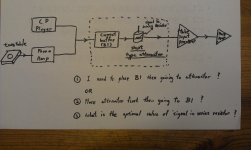
The B1 has two switchable inputs. That's where the two sources connect.
Then the switches should feed the selected signal to the attenuator.
Finally the output of the attenuator is fed to the buffer since the attenuator cannot alone drive the cables to the power amplifier and/or the pre-amp.
Do you really need a pre-amp?
Which signal needs more amplification?
Do that before you send the signal to the attenuator.
Hello Andrew,
Tube preamp was my DIY project finished in few years ago but last year I added B1 buffer on it. All the sound and presentation is slightly better than before. Right now I am replacing my Preamp's 24 steps attenuator by shunt type attenuator (with remote control and has 80 steps). Actually, I want the phono signal can get a better presentation.
My concern is the order arrangement for the shunt type attenuator and B1 buffer. You know the shunt type attenuator drawback is vary of impedance to its next stage. Base on my situation, how following option is better deployment ?
Option 1) Source signal -> Shunt type attenuator -> B1 buffer -> Tube Preamp
Option 2) Source signal -> B1 buffer -> Shunt type attenuator -> Tube Preamp
Another question is how to selection the value of series resistor inside the attenuator ?
The B1 has two switchable inputs. That's where the two sources connect.
Then the switches should feed the selected signal to the attenuator.
Finally the output of the attenuator is fed to the buffer since the attenuator cannot alone drive the cables to the power amplifier and/or the pre-amp..............
...................My concern is the order arrangement for the shunt type attenuator and B1 buffer. You know the shunt type attenuator drawback is vary of impedance to its next stage. Base on my situation, how following option is better deployment ?
Option 1) Source signal -> Shunt type attenuator -> B1 buffer -> Tube Preamp...................
Lowering the output impedance?
I've read that the output impedance of the DCB1 is 260 ohms. The amplifier this will be connected to prefers around 50 ohm output of the pre-amp, although 1K ohm can be supported.
How could I lower (or raise) the output impedance to match the values above?
Thanks
I've read that the output impedance of the DCB1 is 260 ohms. The amplifier this will be connected to prefers around 50 ohm output of the pre-amp, although 1K ohm can be supported.
How could I lower (or raise) the output impedance to match the values above?
Thanks
The output impedance is made up from a combination of the output resistor and the follower's output impedance.
You can change the output resistor for a lower value. But you must check that the adopted value does not allow the B1 to become unstable on fast changing signals/interference.
You can change the output resistor for a lower value. But you must check that the adopted value does not allow the B1 to become unstable on fast changing signals/interference.
Is R4 the correct output resistor to change? If so, would it be a correct assumption to calculate the follower's output impedance as 260 - R4?
R4 = 220ohm, therefore the follower's output impedance is 40ohm
Without a scope, or test equipment (apart from a DMM), how could I check to see if a lower value is causing it to be unstable?
Thanks
R4 = 220ohm, therefore the follower's output impedance is 40ohm
Without a scope, or test equipment (apart from a DMM), how could I check to see if a lower value is causing it to be unstable?
Thanks
That layout is vintage of what later sprung to Mez and Hypno in their popular forms. Nice to see it done again and playing well. Watch turn off cycle mainly if to ever drive a DC coupled amp since there is no relay. Enjoy.
Salas, can you send me the EAGLE files ? I want to build it
I want to etch this
Hi everyone,
I've read all post here from page 1 to last one... need some days
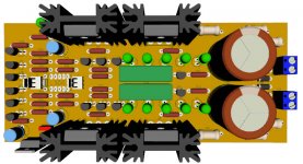
I want to use my own layout, please some comment before I go to etch it PCB
Maybe I miss something important...
Question:
Is that okay to use 2 + 3 LED's (bright one) instead of 3 + 5 LED's...?
(all I need is to match the voltage to 5.4v & 9v)
Regards
Hi everyone,
I've read all post here from page 1 to last one... need some days
I want to use my own layout, please some comment before I go to etch it PCB
Maybe I miss something important...
Question:
Is that okay to use 2 + 3 LED's (bright one) instead of 3 + 5 LED's...?
(all I need is to match the voltage to 5.4v & 9v)
Regards
Attachments
Last edited:
I wouldn't pretend that I have the energy to scrutinize your layout for connections (40C here). Just make sure it follows the schematics accurately.
But others may spot something or not.
Unfortunately super bright LEDS have a reputation for being noisier than normal ones which I can not confirm how much right now.
But surely I have never seen them in instrumentation as voltage references. Better use 3mm generic reds or greens in the 3+5 proven configuration.
- Home
- Amplifiers
- Pass Labs
- Building a symmetrical PSU B1 buffer