Did you try the F5 with another preamp in the same system configuration?
Let me switch it to my Audionet, just a moment...
Hi dvb-projekt, just noticed in the F5 thread that you found someone else with the same issue.
I'd try disconnecting the preamp altogether and running a jumper wire from the earth on one input socket to the earth on the other input socket (assuming they aren't connected already) and see if that causes your hum.
You may be getting an earth loop between channels out one interconnect lead and back in the other.
Tony.
Hi dvb-projekt, just noticed in the F5 thread that you found someone else with the same issue.
I'd try disconnecting the preamp altogether and running a jumper wire from the earth on one input socket to the earth on the other input socket (assuming they aren't connected already) and see if that causes your hum.
You may be getting an earth loop between channels out one interconnect lead and back in the other.
Tony.
Hi Tony,
i have tried it. No hum when the input cables are disconnected, also with the wire between both cinch GND's...
Hi all,
i have a funny problem with my DCB1.

Beacuse the old amp was mono you must have separate wires. Now all at once you connect them to a same ground again: you have now a big loop (Spule) that catches the hum from the mains.
So: wrap the two interconnects around each other (like twisted pairs), tape the two wires together, and presto . . .
hope this helps
Thanks for your suggestion, but the problem is also with other interconnects, see Post #2458 . A bit better but not silent...
Wierd.
I meticulously matched the LEDs that make up the 5.4V drop at the input of the DCB1 using the actual 2SK170BL that would be used in that part of the circuit.
Everything tested perfectly 5.38V at about 9mA (I was using the higher current unmatched 2SK170's.
Now all is soldered together on the PCB I have nearly 100mV difference between +Vcc and -Vcc. The series IRFPs aren't fitted yet so I am measuring at the gate stoppers which are (obviously) open circuit.
With a 15-0-15V transformer I am reading +17.4V and -17.3V.
Is this going to be an issue as the IRFPs aren't matched and the shunt reg should take care of any differences ????
Last edited:
I've got approx 5.38V and the series resistors are currently 22R
I'm aiming for about 200mA - I did ask earlier about the voltage across the series resistors but no-one replied.
Using my BJT knowledge. With Vb at 5.38V, Vbe=0.6V so the voltage across the Emitter resistors needs to be about 4.78V.
I=E/R so I would be 217mA with a BJT. If that is still true with a MOSFET, I just don't know.
So the 5V (3 x LED) are only setting the current through the regs.
Those, the particular Mosfet Vgs, and the particular setting resistor. PMOS and NMOS are not having the same Id-Vgs curve in most cases anyway, no same Mosfet is guaranteed to have the same curve, and so it goes. But not crucial at all.
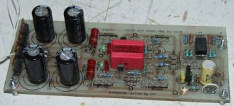
Well I've finished the PSU part of the DCB1.
I've got +/- 9.58V give or take 10mV or one digit on the DMMs.
Running current with the 22Rs is 63mA - a bit lower than intended but everything is running cool.
The voltage seems to be dropping slowly as warm them up, not much but it started at 9.6V and after a 10 min test they were 9.5V.
The IRFPs have no heatsinking, they are cool to the touch.
Next step is to fit the elusive matched 2SK170BLs and then it's finished.
Attachments
Last edited:
- Home
- Amplifiers
- Pass Labs
- Building a symmetrical PSU B1 buffer