Here's my build so far...
Just need to wire up a power switch (to the front or back panel).
hmm, led strings are not quite what was recommended (1.8v drop each).
Other than that, I'm really happy with the build. Most difficult part was drilling out a square hole for that IEC inlet.
Next build I'll hopefully find something that is pre-drilled.
Clean build, nice box.
More listening impressions. My B1/Aleph 5 combo has tons of detail and resolution but is a touch bright and a touch cold for my taste. Since I went from an integrated amp to a buffer/power amp combo I've change two things so it may be awhile before I track down who or what is the culprit.
BTW, the change to higher CCS seems to be all positives. I found more bass, more depth, and more detail. An improvement worth pursuing.
My integrated is a PD gainclone so I'm going to have to do some back to back tests to see which may earn a permanent berth on my component rack.
On the horizon is a lightspeed for my B1 and hopefully a pair of F5 monoblocks. I must say Father Pass's generosity is keeping me very busy!
Regards,
Dan")
BTW, the change to higher CCS seems to be all positives. I found more bass, more depth, and more detail. An improvement worth pursuing.
My integrated is a PD gainclone so I'm going to have to do some back to back tests to see which may earn a permanent berth on my component rack.
On the horizon is a lightspeed for my B1 and hopefully a pair of F5 monoblocks. I must say Father Pass's generosity is keeping me very busy!
Regards,
Dan


Ribbon arrays can throw cylindrically more consistently in the long dimension than their cone neighbors at crossover and up. Have you taken RTA averages on listening seat area? Awesome build by the way.
Although I built these myself, these arrays were designed by Rick Craig of Selah Audio.
Selah Audio
BTW. Now that I've experienced them I can't ever imagine not having line arrays.
Regards,
Dan
Last edited:
As suggested I've changed Rd with a CCS (parallel P jFets to lower Id) and once I realized that I have current amplification and need an R to gnd to have I/U conversion and figured out a correct R value it worked like a charm (at least in sim). All measured Vds's, Id's seamed right and THD dropped to 0.05% for 2.5V RMS out. Not bad for 25db gain, dc coupled line amp (if it's so on the bench as wellI ask because I think it would drop THD.
) I'm a newbie in electronics theory so I have to chew on this and have to listen whether Rd or CCS one I like better.
Thanks! no more off topic...
My B1 is losing the battle in back to back listening tests with my Peter Daniel gainclone. Any suggestions before the B1 risks going on the block?
Regards,
Dan
B1 isn't an amp, what you compare exactly? B1 driving a ClassA amp VS a GC without input buffer? Maybe you would want to drive the GC too with it, and see how it goes? Do the easy film cap mod anyway. If you got 2x 5mm pitch MKP 0.1-0.47uF or other.
Hello,
Testing my b1. The leds don't light up at all, but I hear the output relay clicking. Could someone point me to a circuit schematic. I don't understand when people say "measure voltage across R1". What is R1?
I haven't tried measuring the dc offset. But I think as a first step I should get the leds to light up. Maybe, I have them reversed.
Thanks.
There is a place designated as 2 68R positions in parallel. On both sides near the main filter capacitors. There are 3-3 holes actually so to put 3 100R for the same result if not having 68R. Those are in parallel and form the current setting resistor value. Across those you may find a voltage drop of 1.6-2.3V. Shows around 2V in most builds. That would mean circa 60mA which is the current of the basic set up that will survive without heat sinks.
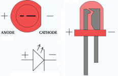
Next to each row of leds there is a D symbol indicating their correct heading. Towards the flat part cathodes go. The schematics are in the first 2 pages.
Next to each row of leds there is a D symbol indicating their correct heading. Towards the flat part cathodes go. The schematics are in the first 2 pages.
- Home
- Amplifiers
- Pass Labs
- Building a symmetrical PSU B1 buffer