hey, where are you guys sourcing your pots from?
I'm having a hard time getting alps rk27 @ 20k for a reasonable price.
yeah, they are really expensive out there. I boughtm ebay an stteped attenuator and soldered all the resistors by my self. It was a bargain, but now I understand why. It fails sooo much times, really bad contacts and suddenly on channel stops sounding. Be aware with extremely cheap products.
I am waiting for a Lightspeed to arrive, it cost a bit more than a good pot to implement, but seems to sound far better that pots.
What temperature did you have on the fets?
I have 2 other shunts and an F5 running hotter than this and survived previous Greek summer with no AC!
Not measuring the nominal, but quite hot that i cant touch it continuosly more than 5 seconds before failed. At the end, the transistor isnt going hot again just warm, then i measured the resistance between the pins, there is thing i said before.
Alright, "without pics it didn't happen...", so let's try this.
Some highlights:
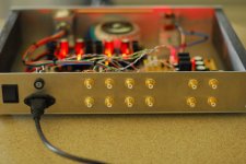
- LDR attenuator (can I say Lightspeed?), powered by Salas mini-shunt (4.86V)
- 2 buffers, (1 hypnotize, 1 mesmerize). Flexibility for my bi-amped system (drive PLLXO's, sum to mono, etc.) Have a single powered sub running at the moment but plan to build cabinets for my Seas Excel W26's eventually (crossover at line level below 300 hz).
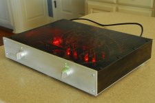
- 4 inputs, simple intuitive LED indicator on front to show selection, pic shows "input 3" is selected. Controls work great, volume typically stays in the 10:00 to 12:00 range at my listening levels. Orange LED indicates center of the LDR range for long life.
- Aluminum mesh top gives a glimpse of the beast within. Looks awesome at night.
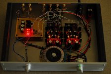
- Increased CCS to just under 100mA (20 ohm, 2 watt at R1), heatsinks only warm, could be increased more, no other "mods" yet.
- SOUND?! Incredibly dynamic and transparent, as advertised. I'm all for "simple as possible" but can find no drawbacks to replacing my "passive pre" with this, only enormous improvement in all areas. Actually shocked at how much better everything sounds. Even sounds fantastic at low volume settings. I can very easily route the output of the attenuator straight to the ouputs bypassing the buffers completely if I wanted (everything on connectors), but have no reason to.
Thank you Salas, CRT, georgehifi (Lightspeed), Tea-bag, udailey, and all others that made this possible. This is one wicked preamp....
Some highlights:
- LDR attenuator (can I say Lightspeed?), powered by Salas mini-shunt (4.86V)
- 2 buffers, (1 hypnotize, 1 mesmerize). Flexibility for my bi-amped system (drive PLLXO's, sum to mono, etc.) Have a single powered sub running at the moment but plan to build cabinets for my Seas Excel W26's eventually (crossover at line level below 300 hz).
- 4 inputs, simple intuitive LED indicator on front to show selection, pic shows "input 3" is selected. Controls work great, volume typically stays in the 10:00 to 12:00 range at my listening levels. Orange LED indicates center of the LDR range for long life.
- Aluminum mesh top gives a glimpse of the beast within. Looks awesome at night.
- Increased CCS to just under 100mA (20 ohm, 2 watt at R1), heatsinks only warm, could be increased more, no other "mods" yet.
- SOUND?! Incredibly dynamic and transparent, as advertised. I'm all for "simple as possible" but can find no drawbacks to replacing my "passive pre" with this, only enormous improvement in all areas. Actually shocked at how much better everything sounds. Even sounds fantastic at low volume settings. I can very easily route the output of the attenuator straight to the ouputs bypassing the buffers completely if I wanted (everything on connectors), but have no reason to.
Thank you Salas, CRT, georgehifi (Lightspeed), Tea-bag, udailey, and all others that made this possible. This is one wicked preamp....
Attachments
Williams,
First, congratulations for your great build. It maybe one, if not the most, complete integrated DCB1 with all those connection options, nice volume control, LED indicator, and demostrating wonderful constructor skills. Amazing mesh cover")
I have some questions about it:
-How does the orange led works? I am interested in this display for the LDR range, haven't ever heard of such a thing...I am going to implement an LDR volume control soon.
-For he CCS, I have heard that the sweet spot could be between 200ma and 250ma because of some characteristic of the MOSFETs at this values. Maybe Salas can give us more info about that.
First, congratulations for your great build. It maybe one, if not the most, complete integrated DCB1 with all those connection options, nice volume control, LED indicator, and demostrating wonderful constructor skills. Amazing mesh cover
I have some questions about it:
-How does the orange led works? I am interested in this display for the LDR range, haven't ever heard of such a thing...I am going to implement an LDR volume control soon.
-For he CCS, I have heard that the sweet spot could be between 200ma and 250ma because of some characteristic of the MOSFETs at this values. Maybe Salas can give us more info about that.
-For he CCS, I have heard that the sweet spot could be between 200ma and 250ma because of some characteristic of the MOSFETs at this values. Maybe Salas can give us more info about that.
You remember well, I have wrote before that for the particular MOSFETS they pick up some transconductance around 200mA. Where they really pick up, you don't wanna hear. They are current beasts.
Thank you guys, I worked hard on this. A drill press sure would have been nice to have, ha! Metal was ordered online cut to size, birch ply side panels cut at a relatives house where I had access to a table saw, and compound miter. Sanded and stained it a nice dark ebony (Minwax #2718) then "clear satin" polyurethane when I got home. The mesh was left over from my diy ESL's, cuts easily with scissors.
The orange LED is really just a "power on" indicator that's there mainly to sort of balance out the look of the front panel, add some interest, and with 40 something LED's already, how about 1 more.... I've read the LDR's will receive the least amount of wear if you keep the volume at 50% if you're leaving this thing on all the time, which I mostly do. So, it made sense to me to put the LED there.
The high CCS seems desirable, but my FETs are not sinked to handle that much. I think it's great even at stock values, the bump up to 100mA was subtle to me, maybe it "needs" more? Maybe not. It really sounds great and I'm super impressed as is.
You remember well, I have wrote before that for the particular MOSFETS they pick up some transconductance around 200mA. Where they really pick up, you don't wanna hear. They are current beasts.
So...time for running a heatsinks group buy?

At 100mA you get some of the benefit. If you can get some MKP 1837 Vishay 10n or FT-1 22nF CCCP Teflon, just bypass the 5 string shunt 100uF lytics underneath pcb, keeping short legs. But not the output lytics. That one you may hear easy and decide, without hacking or altering visually the nice build.
Forgot to mention something important, this preamp is as silent as the grave. With the volume almost maxed, and my ear almost touching the speaker cone, I can not tell if the preamp is on or off, absolute silence. The trick was to tie the two main power supply ground points of the two buffers together underneath with a short run of wire (maybe 18ga? can't remember). Also, the ground of the LDR power supply (and front panel LED's) is in no way connected to the ground of the DCB1's.
- Home
- Amplifiers
- Pass Labs
- Building a symmetrical PSU B1 buffer