Yep, youre right. I messed that up on mine to. Ended up buying two center tapped because I just looked at the 12V rather than the fact that they are adding the two values to get 12. Plus it doesnt have 2 voltage outputs at the same time anyway. Should have looked a lot closer. The 12V or 6V depends on that being series or parallel so its does not have two output voltages at once. Sorry about that.
Wonder if this one would help him.
New Page 2
They claim "110 volt AC input with 2.5, 8, 12, 16 and/or 24 volt AC outputs (called "taps"). We add a line cord for easy hook up. Also works on 220VAC"
And they say you can use all tap voltages at once.
Uriah
New Page 2
They claim "110 volt AC input with 2.5, 8, 12, 16 and/or 24 volt AC outputs (called "taps"). We add a line cord for easy hook up. Also works on 220VAC"
And they say you can use all tap voltages at once.
Uriah
Wonder if this one would help him.
New Page 2
ehh, shouldnt it be center tapped, doesnt look like one
It says "taps", not "center taps"
Digi-Key - MT3143-ND (Manufacturer - PLT20-32-130B)
It has a 27.5VAC CT AND the 9.3V secondary that could be regulated. The 27.5VCT could be used for the DCB1. Its a little high but not by much. With nearly no load it might come in higher voltage but a few watts of resistance might help that. Its the closest I could find on digikey. Which still leaves wondering if it works for VCCS as well.
It has a 27.5VAC CT AND the 9.3V secondary that could be regulated. The 27.5VCT could be used for the DCB1. Its a little high but not by much. With nearly no load it might come in higher voltage but a few watts of resistance might help that. Its the closest I could find on digikey. Which still leaves wondering if it works for VCCS as well.
Hi Guys,
Thought I'd post a progress report.
1. I did the discrete regulator circuit I mentioned in post #865, following the advice given in the posts immediately after. After fiddling around with choosing LEDs, the best I could get was 8.54 and -8.34 VDC, which is a little low when you want +/- 9V, but within reasonable. (I'd rather err on the low side than err on the high side and blow a jfet...) If I wanted to fiddle around selecting leds some more I could probably get it more equal, but I'm not sure it's worth the bother, especially when you remember that I have output caps on it, and it's mainly intended as a test bed. On the other hand, the sound is FAR better than the 7809/7909 reg circuit I was using to test the heat dissipation. I expected some improvement, but I just finished listening to Mahler's 8th on my office system and found the improvement remarkable. OK, the system can't handle the organ, and the PSU in the preamp won't change that, but the improvement was most noticable in the quiet passages, where the soprano and mezzo voices have to be clearly separated (and positioned) from the rest of the (huge) orchestra. I found the difference from the earlier PSU and indeed from my other diy B1 quite striking... (Of course, now I should go back and do a proper AB comparison...)
2. I also followed Salas' suggestion and switched out the 3v9 zener for a LED pair in the big preamp. I tested various pairs until I got exactly the right voltage, so no resistor necessary, but the kids haven't given me a chance to listen to it yet... I still need to plan out the power supply for the active filters I'm doing, which I will likely do (following a suggestion of ZenMod on another thread) using one large current source feeding separate shunts at each buffer. (A total of 10 shunts... ) With this in mind, this thread may be a good place to ask about people's experiences using jfets other than 2SK170... As juma pointed out (elsewhere) I could use the BF862, but it would likely need cascoding, which is OK (if I understand correctly) but increases complexity in an already complex project. So I am on the lookout for other solutions, since 2SK170 are hard to come by down here and are expensive to import. As a sub-question, are the low-noise properties of the 2SK170 more important in the current source than the shunt, perhaps? Any thoughts?
Cheers
Nigel
Thought I'd post a progress report.
1. I did the discrete regulator circuit I mentioned in post #865, following the advice given in the posts immediately after. After fiddling around with choosing LEDs, the best I could get was 8.54 and -8.34 VDC, which is a little low when you want +/- 9V, but within reasonable. (I'd rather err on the low side than err on the high side and blow a jfet...) If I wanted to fiddle around selecting leds some more I could probably get it more equal, but I'm not sure it's worth the bother, especially when you remember that I have output caps on it, and it's mainly intended as a test bed. On the other hand, the sound is FAR better than the 7809/7909 reg circuit I was using to test the heat dissipation. I expected some improvement, but I just finished listening to Mahler's 8th on my office system and found the improvement remarkable. OK, the system can't handle the organ, and the PSU in the preamp won't change that, but the improvement was most noticable in the quiet passages, where the soprano and mezzo voices have to be clearly separated (and positioned) from the rest of the (huge) orchestra. I found the difference from the earlier PSU and indeed from my other diy B1 quite striking... (Of course, now I should go back and do a proper AB comparison...)
2. I also followed Salas' suggestion and switched out the 3v9 zener for a LED pair in the big preamp. I tested various pairs until I got exactly the right voltage, so no resistor necessary, but the kids haven't given me a chance to listen to it yet...
I still need to plan out the power supply for the active filters I'm doing, which I will likely do (following a suggestion of ZenMod on another thread) using one large current source feeding separate shunts at each buffer. (A total of 10 shunts... ) With this in mind, this thread may be a good place to ask about people's experiences using jfets other than 2SK170... As juma pointed out (elsewhere) I could use the BF862, but it would likely need cascoding, which is OK (if I understand correctly) but increases complexity in an already complex project. So I am on the lookout for other solutions, since 2SK170 are hard to come by down here and are expensive to import. As a sub-question, are the low-noise properties of the 2SK170 more important in the current source than the shunt, perhaps? Any thoughts?Cheers
Nigel
Thanks guy! I'll have a look for the transformer...
@Salas, can you check the Ampere used by your own DCB1 please? ...so during my transformer (with multiple secondary) search, I could take the correct rating...
Its what the 2 CCS draw, relays, plus losses in the Tx and rectification. Depends on how hard you run the CCS, other auxiliary circuits like the realys or LSPD if used, add 20% on top of that as min. I would double that for comfort.
I tried a new pot in my DCB1 tonight. For those on a budget (or not actually) these are fantastic value:
DACT Type 21 Stepped Attenuator 20K FOR PASS B1 DIY - eBay (item 120502791204 end time Feb-04-10 09:17:39 PST)
So how does it sound? Well, very good actually. The sound is a bit warmer than with the lightspeed, and to be absolutely honest, in my system, thats probably a plus. The soundstage is not as distinct, or maybe resolving, as the lightspeed, but its very nice. The action on the pot is nice, the detents are very smooth/gentle not very "clicky" if you know what I mean. The other one to compare it to is the valab one, which is 25$. In terms of sonics, I don't think the valab one is any better, but I'd say the switch quality in the valab one is probably better. Having said that, there are lots and lots of open case pots out there working AOK.
No clicks, pops etc on turning. Feel wise, I think this is one of the nicest yet. At that price an absolute steal.
I'm going to leave it in for a while and see how it goes....
Fran
I tried a new pot in my DCB1 tonight. For those on a budget (or not actually) these are fantastic value:
DACT Type 21 Stepped Attenuator 20K FOR PASS B1 DIY - eBay (item 120502791204 end time Feb-04-10 09:17:39 PST)
So how does it sound? Well, very good actually. The sound is a bit warmer than with the lightspeed, and to be absolutely honest, in my system, thats probably a plus. The soundstage is not as distinct, or maybe resolving, as the lightspeed, but its very nice. The action on the pot is nice, the detents are very smooth/gentle not very "clicky" if you know what I mean. The other one to compare it to is the valab one, which is 25$. In terms of sonics, I don't think the valab one is any better, but I'd say the switch quality in the valab one is probably better. Having said that, there are lots and lots of open case pots out there working AOK.
No clicks, pops etc on turning. Feel wise, I think this is one of the nicest yet. At that price an absolute steal.
I'm going to leave it in for a while and see how it goes....
Fran
Great to hear, I picked up a couple myself (and posted about it awhile back).
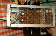
My p2p built DCB1 is finished! And it's running OK! Horrrayy!
PSU voltages: +10.3 and - 9.94 VDC.
DC offset: 0.8 and 1.3 mV - with the initial LEDs, I didn't have to replace any of them!
Pictures here. Case is not too pretty, I even made some unimportant mistakes, but I was too tired and a bit disappointed after the F2 experience, so i didn't care to remedy them.
I have skipped the relays part. R1 in the PSU is 11 ohms (2x22 ohms in parallel); sinks are too big, but I wanted to be sure ; pot is external for the moment and all I had was a 50k ALPS Blue, so I replaced the 220k in the buffer with 560k. Hope to change it for the above mentioned 20k stepped soon and perhaps a Lightspeed later on, right now I'm short of money - badly!
About the sound I cannot comment much yet, I have tried it with my Mackie HR824 active monitors and it does sound fuller than solely with the pot, but I was with a guest and I didn't have time and proper conditions for a better assessment. I'm not even sure the Mackies are DC protected, btw. And I'm moving to another town in 3 days, so the audio hobby will have to take a (short) break.
Many many thanks to Mr. Pass and Salas as the authors of the "B1" and the "DC", respectively, and also to all the other members here whose knowledge and willingness to help are much appreciated!
I have a couple of questions, though:
1. I hear a hum that I'm 99% sure is a ground loop as I stupidly used some female RCA connectors that touch the ground to the chassis. Instead of buying and soldering other connectors, can I just unsolder the ground from all the connectors and connect the circuit ground to the chassis in a single point elsewhere? This way the signal input ground would be connected to the circuit (= output) ground through the chassis itself: input cable ground --> male RCA connector ground --> female RCA connector ground --> chassis --> circuit ground (and similar for the output). Would this be detrimental to the sound quality?
2. Should I decide to build an F5 instead of my F2 that I have some problems with atm, where would I have to insert a capacitor in the DCB1 + F5 combo? Can it be at the F5 input? Sorry, I'm sure this has been asked before, but I can't find where right now... Also, what value should that capacitor be, can it be 1 uF?
Thanks again!
PSU voltages: +10.3 and - 9.94 VDC.
DC offset: 0.8 and 1.3 mV - with the initial LEDs, I didn't have to replace any of them!
Pictures here. Case is not too pretty, I even made some unimportant mistakes, but I was too tired and a bit disappointed after the F2 experience, so i didn't care to remedy them.
I have skipped the relays part. R1 in the PSU is 11 ohms (2x22 ohms in parallel); sinks are too big, but I wanted to be sure
; pot is external for the moment and all I had was a 50k ALPS Blue, so I replaced the 220k in the buffer with 560k. Hope to change it for the above mentioned 20k stepped soon and perhaps a Lightspeed later on, right now I'm short of money - badly! About the sound I cannot comment much yet, I have tried it with my Mackie HR824 active monitors and it does sound fuller than solely with the pot, but I was with a guest and I didn't have time and proper conditions for a better assessment. I'm not even sure the Mackies are DC protected, btw. And I'm moving to another town in 3 days, so the audio hobby will have to take a (short) break.
Many many thanks to Mr. Pass and Salas as the authors of the "B1" and the "DC", respectively, and also to all the other members here whose knowledge and willingness to help are much appreciated!
I have a couple of questions, though:
1. I hear a hum that I'm 99% sure is a ground loop as I stupidly used some female RCA connectors that touch the ground to the chassis. Instead of buying and soldering other connectors, can I just unsolder the ground from all the connectors and connect the circuit ground to the chassis in a single point elsewhere? This way the signal input ground would be connected to the circuit (= output) ground through the chassis itself: input cable ground --> male RCA connector ground --> female RCA connector ground --> chassis --> circuit ground (and similar for the output). Would this be detrimental to the sound quality?
2. Should I decide to build an F5 instead of my F2 that I have some problems with atm, where would I have to insert a capacitor in the DCB1 + F5 combo? Can it be at the F5 input? Sorry, I'm sure this has been asked before, but I can't find where right now... Also, what value should that capacitor be, can it be 1 uF?
Thanks again!
Attachments
You are welcome.
1. Try that grounding change you thought of. It may work, if that is actually the only grounding problem.
2. F5 must be 100K load if I recall correctly, so 1uF in series with its input must be enough, and the correct place for a single coupling cap in a DCB1S+F5 system.
1. Try that grounding change you thought of. It may work, if that is actually the only grounding problem.
2. F5 must be 100K load if I recall correctly, so 1uF in series with its input must be enough, and the correct place for a single coupling cap in a DCB1S+F5 system.
Any issues with using the DCB1 to drive both a power amp and a sub, i.e. dual outputs?
Its a buffer. Not 0 Zout but adequate. Will make do. Its output resistor normally counteracts ringing. If in a problematic situation, up in value.
I have three outputs, I cannot tell of a problem. I use 100ohm resistors between them on the signal side. I dont remember where I got the recommendation to do this.
OK, thanks. So all outputs connected to output of DCB1, and 100R between each output. Curious to know the reason too.
- Home
- Amplifiers
- Pass Labs
- Building a symmetrical PSU B1 buffer