I would put the stronger one lower between a close enough match. Like 0.2mA dif. Not like a 6 with a 7 or an 8 with a 9 etc.
So the lower one has a bit higher Idss just as I understood earlier ?
I changed them today for 8,08 mA upper and 8,15 mA for the lower FETs. Result: - 3.8 mV and - 4,2 mV offset. This was still without matching the LEDs.
So the lower one has a bit higher Idss just as I understood earlier ?
I changed them today for 8,08 mA upper and 8,15 mA for the lower FETs. Result: - 3.8 mV and - 4,2 mV offset. This was still without matching the LEDs.
Thats an excellent result for the fast approach. I have mentioned some ''esoteric measures''
") that I have inbuilt towards it being a DC coupled but forgiving enough DIY. Did you apply it in your sound system yet?
that I have inbuilt towards it being a DC coupled but forgiving enough DIY. Did you apply it in your sound system yet?Thats an excellent result for the fast approach. I have mentioned some ''esoteric measures''
I only tested the prototype and I was quite satisfied with it although it was not far from breadboard status. The two I am working on are finished ( and built with better parts ) except that I am waiting for the cables that a friend will crimp for me. Been away last week so as usual it delayed. Count that delay with the lack of time because of work and you'll know the story.
One of them will play within a week or 2 I guess. Encased that is ! I bought a stepped drill a while ago so drilling the holes for the RCA connectors won't be a problem this time.
BTW are the values for the LED strings really that critical ? I have 5,78 over the 3 LEDs and 9,4 V over the 5 LEDs. All yellow LEDs.
And what about bypassing the 100 uF caps ? I am surprised no one has mentioned it (yet ). Or do you think that is not necessary ?
Last edited:
The +/- 10Vout target area which is reached in accordance to mostly Vf and vref's running current is a subjective ''sweet spot'' as I have found with 7-8mA BL. Back in the B1 thread when I was testing voltages on the fresh prototype with series regs, Nelson Pass had augmented my notion by an agreeing post about better areas actually existing for Jfets, saying that he even got some data if you remember. See to have about 0.2-0.5V positive diff slight asymmetry for +/- 9.5 to 11V Out. Also less than 5mV DC offset is more than good. So if you are in that ballpark is OK. Enough matched but not that hard matched will do. You got snug very nicely where I targeted it, that shows that your Leds are well chosen from datasheet and near tolerance. Yours is OK. No further action needed.
Don't bypass the 100uF caps as a given upgrade IMHO. Everytime an electrolytic is bypassed as such with 0.1uF etc. I can perceive hardness. Maybe you know some nicely working combination of types and makes from other applications, then only try. In general I prefer a straight Silmic II, Pana FM, Nichicon FW, Elna BG, from some small compact cap bypass. Maybe an RC Zobel with a small R and 1uF film could do better than a straight film bypass. Tip: The more sensitive to subjective alterations position, is the 5 Leds bypass position. But I leave such play with 100uF makes and bypasses to you guys, so to enrich the thread.
Also, if prepared to really sink the thing either on thick enough metal enclosure floor or on big enough sink by mounting the Mosfets like in power amps, underneath with bent legs, you can lower the current set resistors combination value to 10R 5W each side and cruise the regs around 200mA. That, you will hear.
Well, I powered mine up tonight!! She lights up like a christmas tree and all seem well.
I get 10.1V and 9.6V at the output of the shunt - on an exceptionally low line voltage tonight of 220V. Tx were putting out 10.6 and 11.2VAC - normally this is a little above 12VAC (this could be why the neg reg has a slightly lower output).
The muting relay clicks in after about 5secs. The other relays all work AOK, tested by shorting the input pins to gnd.
Salas - the 270R for the V-drop for the 6V relays worked AOK,they are being fed 6.2V. I have a clip-on heatsink on the 7812 but its cool - could get away without one handy enough I'd say.
No buzzing or anything with the BC550 instead of the BC517.
2 separate transformers seem to work AOK.
DC on the outputs: 0.3mV and 1.3mV after being on for ~30mins
IRFP140/9140 barely get warm sitting on the bench (admittedly fairly cold out in the workshop tonight.
Thats all I can think of right now. My chassis is coming on well, but I have yet to make the lightspeed attenuator for it. I plan on just shorting the pot to start with just to test out first....
Fran
PS. Salas, that mention of 5W 10R - a single one of these to replace the paralleled 68R? Mine will sinked on a large 3mm alu plate....
Your Tx secondaries are below spec when you have low mains. You need to measure the DC voltages on the main filter caps and the voltage drops across the 3 Led strings & 68R//68R and let me know.
Yes a single 10R 5W will do so to run the shunts high if you fancy. But run the system in using some normal pot so to get acommodated with its sound before you will either up the CCS current and/or add the LSPD, so to appreciate and communicate your impressions better.
Yes a single 10R 5W will do so to run the shunts high if you fancy. But run the system in using some normal pot so to get acommodated with its sound before you will either up the CCS current and/or add the LSPD, so to appreciate and communicate your impressions better.
OK. I have an ebay stepped pot that I might stick in just for now. Its a 50k but at least I'll get a handle on the sound. I had that in the "normal" B1 first and noticed how I got more clarity when I moved to the LS there. It would be good I suppose to follow that same methodology here.
Fran
Oh yeah, I'll do the measurements you suggest later tonight....
Fran
Oh yeah, I'll do the measurements you suggest later tonight....
Measurements:
V at filter caps: 13.8 and 13.8V
Drop across the 3 LEDs: 5.45 and 5.49V
Drop across the //68R: 1.789 and 2.150
Line is low again tonight at 219VAC. Every other time I have ever measured it, its been >230V. Maybe I would be better with a transformer with 15V secondaries?
Fran
V at filter caps: 13.8 and 13.8V
Drop across the 3 LEDs: 5.45 and 5.49V
Drop across the //68R: 1.789 and 2.150
Line is low again tonight at 219VAC. Every other time I have ever measured it, its been >230V. Maybe I would be better with a transformer with 15V secondaries?
Fran
The +/- 10Vout target area which is reached in accordance to mostly Vf and vref's running current is a subjective ''sweet spot'' as I have found with 7-8mA BL. Back in the B1 thread when I was testing voltages on the fresh prototype with series regs, Nelson Pass had augmented my notion by an agreeing post about better areas actually existing for Jfets, saying that he even got some data if you remember. See to have about 0.2-0.5V positive diff slight asymmetry for +/- 9.5 to 11V Out. Also less than 5mV DC offset is more than good. So if you are in that ballpark is OK. Enough matched but not that hard matched will do. You got snug very nicely where I targeted it, that shows that your Leds are well chosen from datasheet and near tolerance. Yours is OK. No further action needed.
Don't bypass the 100uF caps as a given upgrade IMHO. Everytime an electrolytic is bypassed as such with 0.1uF etc. I can perceive hardness. Maybe you know some nicely working combination of types and makes from other applications, then only try. In general I prefer a straight Silmic II, Pana FM, Nichicon FW, Elna BG, from some small compact cap bypass. Maybe an RC Zobel with a small R and 1uF film could do better than a straight film bypass. Tip: The more sensitive to subjective alterations position, is the 5 Leds bypass position. But I leave such play with 100uF makes and bypasses to you guys, so to enrich the thread.
Also, if prepared to really sink the thing either on thick enough metal enclosure floor or on big enough sink by mounting the Mosfets like in power amps, underneath with bent legs, you can lower the current set resistors combination value to 10R 5W each side and cruise the regs around 200mA. That, you will hear.
Thanks for all the time and answers. I won't sink more current as I am very ( too ?) conservative with useless heat and waste power. IMO when people would be somewhat more conscious about energy we would not have the problems we have today in this world. It all starts with small things ...
Last edited:
Measurements:
V at filter caps: 13.8 and 13.8V
Drop across the 3 LEDs: 5.45 and 5.49V
Drop across the //68R: 1.789 and 2.150
Line is low again tonight at 219VAC. Every other time I have ever measured it, its been >230V. Maybe I would be better with a transformer with 15V secondaries?
Fran
52 & 63mA running current. I would like to see 16-17V on the caps so the CCS could reject wider ripple amplitudes as a margin, but I doubt you get any more than in 100-200mV range. If when you listen to it, you still can't perceive any roughness, then you should be OK. Else, you should up the secondary specs with the mains low plateaus you experience.
Thanks for all the time and answers. I won't sink more current as I am very ( too ?) conservative with useless heat and waste power. IMO when people would be somewhat more conscious about energy we would not have the problems we have today in this world. It all starts with small things ...
It will still sound as intended, which is good enough. I don't crank up either. But if someone already has an F5 for instance, will not hesitate... If China will not turn ecological, Polar bear's future is
 in the big picture anyway.
Last week I had an engineer over that had recently installed a large quantity of UPSes in a chinese factory. He told me he was surprised to see mostly 4 stroke scooters in Beijing nowadays. It's a start.
I really hope that they will learn from our mistakes, how hypocrite it may seem. Suppose they make all the same errors...life will be difficult for the whole planet if so.
I really hope that they will learn from our mistakes, how hypocrite it may seem. Suppose they make all the same errors...life will be difficult for the whole planet if so.
Last edited:
Thanks Salas,
I will watch the line voltage over the next few days and see what happens, but that is unusually low. We have had serious rain, of biblical proportions here in the past week with many areas flooded. I know lots of places are without electricity, so undoubtedly all that is connected in with my low line voltage.
I got the source selector switch wired up tonight. I used a 2 pole, 6 position switch, set to 4 positions and I added in some LEDs on the other pole as indicators. I used the 12V supply before the Vdrop resistors for the relays with a 1K in series. Works a charm.
Volume pot is next on the list, then after some listening, get the lightspeed made and hooked up.
Thanks for the help so far.
Fran
..far off topic........Last week I had an engineer over that had recently installed a large quantity of UPSes in a chinese factory. He told me he was surprised to see mostly 4 stroke scooters in Beijing nowadays. It's a start.
Uh, I thought they mostly rode around on bicycles? Scooters sounds like a start, to using more petrol.
I seem to recall reading somewhere that because of the rising incomes Chinese are more likely to purchase an automobile.
..apologies, back to our regularly scheduled topic...
Thanks Salas,
We have had serious rain, of biblical proportions here in the past week with many areas flooded. I know lots of places are without electricity, so undoubtedly all that is connected in with my low line voltage.
Fran
Fran,
I heard on the news about the flooding problems and rain.
Last month our area set a record for rain for the month, 3x the last record I believe.
I know - luckily the area I live in is dry - even after all the rain, my yard was dry - not a single puddle!
Lots badly affected though. One shopkeeper said that his insurance used to be 4k, he was flooded 8 years ago (not as badly as this one) and afterwards they wanted to up his premium to 32k - and that had an exclusion for flood damage!! So most o these people are without insurance now.
Yes, back to topic now, sorry for being OT there.....
Fran
I sell LSK170 in matched pairs to UK buyers. Payments and posting are simply when internal.AndrewT's prices are better than anyone out there for matched sets. Not only better but a real bargain.
Uriah
I now add a premium to International orders for all the extra work and particularly the travelling to the post office (14miles each way).
BTW.
the B1 and the shunt regulator do not need matched pairs.
The B1 just needs selected Idss. No matching is required.
One quick (very) newbie question. If going for a DCB1 with a Lightspeed attenuator can I use a single 48VA 2x12V transformer for both? If yes, how?
Edit: if not, what kind of transformer would be needed for a Lightspeed linear regulated PSU? Sorry if this derails from the thread topic, but my main question is about integrating the DCB1 with the LS...
Edit: if not, what kind of transformer would be needed for a Lightspeed linear regulated PSU? Sorry if this derails from the thread topic, but my main question is about integrating the DCB1 with the LS...
Last edited:
DQ: just look at the wiring diagram on the side of the transformer - join the 2 wires representing the centre of each winding together (=centre tap). Then you have 12-0-12. Check voltages before hooking up.
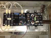
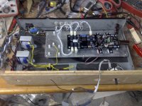
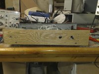
Thought I'd add a few pics up here.
Sorry for the fairly crappy phone pics.... the wooden front will match my F5.
Fran
Thought I'd add a few pics up here.
Sorry for the fairly crappy phone pics.... the wooden front will match my F5.
Fran
Attachments
Thanks Fran (and by the way congrats for your built). I knew I can get 12-0-12 from 2 x 12-0, but I can't relate your answer to my question, sorry. Knowing so little makes one feel so... stupid
Perhaps I should rephrase a bit. And sorry, while I love music I now very little about electronics as you can easily notice.
The trafo that was suggested to me earlier on this thread gives me 2 x 12V (12-0-12, if you like). Say one secondary rail (did I say it right into English?) goes to the DCB1 PSU positive reg. for instance. The other secondary rail goes to DCB1 PSU negative reg., but also to another couple of bridges and a cap (can be identical the the ones in the DCB1 PSU) that would give me the DC voltage for the Lightspeed. Would such an asymmetry be alright for the DCB1? I think the Lightspeed draws constant current, but I'm not sure.
Also, if the above is OK, would the 48VA power rating of the transformer be enough for both DCB1 and LS?
You may all laugh if this idea is so obviously wrong, but please tell me why.
Perhaps I should rephrase a bit. And sorry, while I love music I now very little about electronics as you can easily notice.
The trafo that was suggested to me earlier on this thread gives me 2 x 12V (12-0-12, if you like). Say one secondary rail (did I say it right into English?) goes to the DCB1 PSU positive reg. for instance. The other secondary rail goes to DCB1 PSU negative reg., but also to another couple of bridges and a cap (can be identical the the ones in the DCB1 PSU) that would give me the DC voltage for the Lightspeed. Would such an asymmetry be alright for the DCB1? I think the Lightspeed draws constant current, but I'm not sure.
Also, if the above is OK, would the 48VA power rating of the transformer be enough for both DCB1 and LS?
You may all laugh if this idea is so obviously wrong
, but please tell me why.- Home
- Amplifiers
- Pass Labs
- Building a symmetrical PSU B1 buffer