Hey, don't drain the pool if 100's aren't to be used. The guy sells matched pairs too.")
In Germany, easy for EU members http://www.hifituning24.de/0000009b...21cca/0000009c51086a415/0000009b340c28bce.php
In Germany, easy for EU members http://www.hifituning24.de/0000009b...21cca/0000009c51086a415/0000009b340c28bce.php
Everyone in the states should have theirs (one exception).
Don't tell me that person is you !
BTW after having been busy for too long with pairing FETS and LEDs I just built one with yellow unmatched LEDs and Jfets with 7,5 mA ( upper ) and 8,8 mA ( lower ). I ended up with 10,5 V + and 10,3 V -. At the outputs I have 37 mV offset. Not bad considering I did not pair a thing I think ?
I received new Jfets today and I will continue pairing to get the offset down.
Last edited:
Mouser does not seem to have any 2SK170... at leastnot for 8 weeks!!!
Anybody out there have some Jfet's they wanna let go of???
Or a link will do just fine
Thanks
Spencer in this site can sell even matched sets - many have bought from him.
Also ebay has many hong kong sellers selling this FET.
You can try reading this thread for more such sources for this item
Kannan
The lower Jfets are supposed to have a higher Idss isn't it ? At least that is what I understood from various posts.
I would put the stronger one lower between a close enough match. Like 0.2mA dif. Not like a 6 with a 7 or an 8 with a 9 etc.
So I got to soldering mine together tonight and all went well - so far at least. I have a couple of questions - I would appreciate it if anyone can help...
1. Is it OK to use 2 separate 12V transformers rather than a centre tapped one?
2. I'm using 4 relays + muting (ie total of 5 relays) on my build. These are 6V NAIS ones. What size resistor for these would anyone know? I'm guessing about 300R or so....
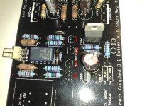
3. Matching of sk170s - I have lots of matched pairs - but what is the orientation on the board - see the pic, are 1and 2 matched, then 3 and 4?
Observations:
Matching the LEDs was more of a pain than I thought it would be. I have a real christmas tree set up now!! A mix of red, yellow and red!! But I got CCS strings at 5.420 and 5.428 and the Vrefs at 9.01 and 9.046. BTW, I bougth the yellow ones as per the BOM from mouser and every one of them are really close to each other at about 1.94 or so. I had a mix of older LEDs knocking about and pressed some of them into service. I had some HLMP6000 agilent ones and they were down at about 1.6V or so.
Other than that, all went very well (I hope!!).
Many thanks in advance.
Fran
1. Is it OK to use 2 separate 12V transformers rather than a centre tapped one?
2. I'm using 4 relays + muting (ie total of 5 relays) on my build. These are 6V NAIS ones. What size resistor for these would anyone know? I'm guessing about 300R or so....
3. Matching of sk170s - I have lots of matched pairs - but what is the orientation on the board - see the pic, are 1and 2 matched, then 3 and 4?
Observations:
Matching the LEDs was more of a pain than I thought it would be. I have a real christmas tree set up now!! A mix of red, yellow and red!! But I got CCS strings at 5.420 and 5.428 and the Vrefs at 9.01 and 9.046. BTW, I bougth the yellow ones as per the BOM from mouser and every one of them are really close to each other at about 1.94 or so. I had a mix of older LEDs knocking about and pressed some of them into service. I had some HLMP6000 agilent ones and they were down at about 1.6V or so.
Other than that, all went very well (I hope!!).
Many thanks in advance.
Fran
Attachments
Last edited:
1. Never done it.
2. Check the Nais PDF, see the current consumption of each 6V Nais. Multiply it by as many you use. Use Ohm's law for a total resistor value of the parallel ones so you drop 6V across them from the 12V available.
3. 1+2 one channel, 3+4 other channel.
*Most protos were OK with BC550. If you get the darn buzz though, strap 150n Ceramic or Polyester between C,B of the lower 550 underneath if with no 517. It proved a perfectly good band aid cure. That is why 150n is in the BOM, rescue for the 517less guys with a knack for jinx.
OK, thanks Salas..
The NAIS relays are 23mA each. So I have 5 in total - thats 115mA total - as opposed to 7 in the normal mesmerize with 28mA each = nearly 200mA. So higher resistance needed. Need to work that out, but bed calls. Maths is not my strong point!
I can't see anything wrong with using 2 transformers back to back like that. I suppose I'll find out when I fire her up!
Fran
Fran
1. Is it OK to use 2 separate 12V transformers rather than a centre tapped one?
I hope I'm not repeating a question here. What is the preferred transformer? The BOM states 2x12V which I interpreted as 0-12/0-12. Should I look at a 12-0-12?
Thanks,
Jeroen
A center tapped 12-0-12 is electrically equivalent to a 12+12 with mid wires together. The difference is that you can not use the center tapped one in some configurations like with double bridges for instance. Irrelevant here. Fran means to use 2 physically separate transformers, not one with 2 secondaries, for as much I gathered.
A center tapped 12-0-12 is electrically equivalent to a 12+12 with mid wires together. The difference is that you can not use the center tapped one in some configurations like with double bridges for instance. Irrelevant here.
Thank you!!
Phew, I ordered the correct one.
- Home
- Amplifiers
- Pass Labs
- Building a symmetrical PSU B1 buffer