Photo
http://picasaweb.google.com/udailey/DCB1#5389663782095010674
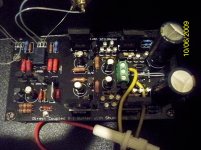
Here is a pic and then another a little bigger in the link. Same pic though.
I tried removing the LED near the 7812. The pads disappeared. Is that LED for anything except indicating power on?
Uriah
http://picasaweb.google.com/udailey/DCB1#5389663782095010674
Here is a pic and then another a little bigger in the link. Same pic though.
I tried removing the LED near the 7812. The pads disappeared. Is that LED for anything except indicating power on?
Uriah
Attachments
Sorry, but how and who do we pay to for the boards? Can we pay by paypal and the shipping fees, is it flat rate for international shipping?
pmchoong,
Go to the link on my signature. My paypal address is highlighted in column J.
Shipping is flat rate per everybody, explained as well in column J.
The Led is to indicate power on. Its cathode (cut circle part) looks towards the near board's edge. Don't worry, you will put a couple of wires from there in the end to get to the front panel for a meaningful ''on'' led. Can you measure the two fat brown parallel resistors to the left, when power is off for me? How many Ohm? Also those 2 between the 7812 and 100uf please. What type of NPNs you use for the delay circuit (those two back to back ones on the left).
http://picasaweb.google.com/udailey/DCB1#5389663782095010674
Here is a pic and then another a little bigger in the link. Same pic though.
I tried removing the LED near the 7812. The pads disappeared. Is that LED for anything except indicating power on?
Uriah
What model of 7812 did you use?
Are the NPN the silver faced bc546's I sent?
The led is just a power on LED. It mounts like the N-channel or normal plus rail ones mount, opposite of the ones on the negative rail.
With this board (and others) I leave a lead on the component, soldering and desoldering, and I heat that first, not the pad, and draw the components out that way, often clipping them off by the head first....I then clean up mess with solder wick as needed. if you have eagle eye's you can drill yourself a tap into the copper trace for the led's and make another connection to it.
The two 600R resistors measure 300 since they are in parallel. The other two the resistance is printed on them 10k and 47k but both measure a very dynamic resistance in circuit. They start low and raise up in resistance. The 47k makes it to 47k and the 10k makes it to a little bit over 7k.
Both are BC546 from Fairchild.
Uriah
Both are BC546 from Fairchild.
Uriah
The two 600R resistors measure 300 since they are in parallel. The other two the resistance is printed on them 10k and 47k but both measure a very dynamic resistance in circuit. They start low and raise up in resistance. The 47k makes it to 47k and the 10k makes it to a little bit over 7k.
Both are BC546 from Fairchild.
Uriah
The two resistor one side nearer to 7812 output is measuring 11.9V - what is the voltage on the otherside - from ground - it should be around 5V if things are working all right?
What is the voltage across the relay coils ?
these measurements should point to any problems that you may have - also measure the voltage on those two transistors
If there is no proper voltage on the relay coils it will not energize
kannan
http://picasaweb.google.com/udailey/DCB1#5389663782095010674
Here is a pic and then another a little bigger in the link. Same pic though.
Uriah
Question. Where is the mid wire from PTx on the phoenix connector? I can't locate it on the pic.
Yes, 180R from Parallel 600Rs to BC546.
BC546 are the ones you sent, thank you")
LM7812 is Fairchild LM7812ACT
The 47k resistor has 11.91V on one side and 8.55 on the other. The 10k resistor has 11.91 on on side and 0 on the other. The Two 600R have 11.91 each side.
The voltage across the relay coil I measured by putting one lead on each side of the diode since it is easily accessible and is parallel to the coil. 0V on the diode.
The midwire, the black one, from the transformer goes to the middle inlet on the terminal block. One yellow wire on either side. So GND is in the right place.
Kannan did you want me to measure the two BC546? I think so. So I measured the leftmost pin on each one. 11.91 on the bottom one and the top goes up slowly to 8.55.
Uriah
BC546 are the ones you sent, thank you
LM7812 is Fairchild LM7812ACT
The 47k resistor has 11.91V on one side and 8.55 on the other. The 10k resistor has 11.91 on on side and 0 on the other. The Two 600R have 11.91 each side.
The voltage across the relay coil I measured by putting one lead on each side of the diode since it is easily accessible and is parallel to the coil. 0V on the diode.
The midwire, the black one, from the transformer goes to the middle inlet on the terminal block. One yellow wire on either side. So GND is in the right place.
Kannan did you want me to measure the two BC546? I think so. So I measured the leftmost pin on each one. 11.91 on the bottom one and the top goes up slowly to 8.55.
Uriah
And the long gnd jumper is soldered in both sides? The way the inwards NPN goes up is OK, there is continuity to the relay and 180R is its spec coil Ohmic, then a dead BC546 speculation remains. Do you have any cbe npn to substitute? Just any. Can you read V also in the mid leg of the lower npn?
People asking about the BOM to order parts, the latest published one was here:
http://www.diyaudio.com/forums/showthread.php?p=1915585
There may be some minor changes coming up but the bulk of it is there.
http://www.diyaudio.com/forums/showthread.php?p=1915585
There may be some minor changes coming up but the bulk of it is there.
People asking about the BOM to order parts, the latest published one was here:
http://www.diyaudio.com/forums/showthread.php?p=1915585
There may be some minor changes coming up but the bulk of it is there.
Korben69 should post the version 3.6 BOM to the other thread or here.
The 3p females are not correct. I have got Mouser to give me the correct one's and have given them to Korben69. I have ordered them myself to insure they fit. Another point is the 2 X 15v listed is preffered to be 2 X 12 50va.
I added and edited some in the unofficial and unapproved building guide. I think that's about it for now. Hope it is helpful. Of course, Salas wrote most of it
You can add this for builders
- use 7812 voltage regulator only even for 5V relay use and then use Resistors ( 2 x600 Ohms) to drop the Voltage down to 5V for relay coils.
Once powered check whether there is a click sound after 5-7 seconds delay on powering up. This indicates relay is working correctly. Measure Voltage across the Diode fitted across relay coil for knowing the voltage. If not something to be corrected on switch on delay circuit
Check all LEDs light up when powered ( if there is a fault some LEDS will not light up- my experience in building this)
- Home
- Amplifiers
- Pass Labs
- Building a symmetrical PSU B1 buffer