Ask again....
Excuse me....
Are Allen Bradley (AB) resistors suitable to be used in this buffer? Which path is more suitable to use this AB resistors? I heard that this resistor is tend to drift up the resistance value due age and high voltage, but adding more enjoyable sound colouring.
Referred to post #75, recomended the 220R to be a good quality resistor. What is good quality resistor? I have AB, Rhoderstein, Dale, unknown carbon film, and unknown metal film for this value. Which one is recomended? Why this value is recomended to use good quality resistor while the others not?
Thanks
Hi,Why this value is recomended to use good quality resistor while the others not?
a bad resistor is one that
changes value with temperature.
or
changes value with voltage
or
changes value with time
or
changes value with humidity
or
changes values with mechanical strain
or
has a value that does not match what it says on the tin.
or
a few others that I have not remembered.
Reducing all of these variations moves one closer to a good resistor.
One can never eliminate all of these variations, no matter how much money one is prepared to pour into the pot.
So the point is to meet the closest value based on the schematic?
Phew...that was close to me using bad resistor
So, it would be better to find a 0,1% tolerance within schematic value. The answer is Roederstein right? I already have it, just not sure which one should be use?
Thanks for the answer
Phew...that was close to me using bad resistor
So, it would be better to find a 0,1% tolerance within schematic value. The answer is Roederstein right? I already have it, just not sure which one should be use?
Thanks for the answer
Excuse me....
Are Allen Bradley (AB) resistors suitable to be used in this buffer? Which path is more suitable to use this AB resistors? I heard that this resistor is tend to drift up the resistance value due age and high voltage, but adding more enjoyable sound colouring.
Referred to post #75, recomended the 220R to be a good quality resistor. What is good quality resistor? I have AB, Rhoderstein, Dale, unknown carbon film, and unknown metal film for this value. Which one is recomended? Why this value is recomended to use good quality resistor while the others not?
Thanks
The 220R are gate stoppers and output dampers for capacitive interactions. The ABs are good for stoppers because carbon. The absolute value determines nothing critical in this circuit, as long as it is roughly 220R. Your best sound is Shinkoh though, if you have access. The resistors here are for terminating the pot, the inputs etc. Not critical for accuracy, but you will listen to them in such a minimal circuit. Chose by ear in your system. Don't change the recommended values, but near as 215R is OK.
I see...
The 220R (gate stoppers and output damper) are giving the significant differences using difference resistor. Okay, I'm gonna try it myself to choose which one is suite on me.
I myself still curious about the 'magic' of resistor, hope I would aware the differences. But if I can't, still ok, not a big deal.
A little share here,
I made regulated power supply B1 buffer before, and compare it with this symmetrical shunt regulated. Then I was awesomed by the performance of this symmetrical buffer. It has more dynamic at low and detail at high. The regulated PS buffer has more thick mid, but for the total hearing i prefer the symmetrical.
For the info, the symmetrical using relatively cheaper components (you know crt, he is the type who dont like 'expensive things'). But for the tonal quality I actually prefer the regulated power supply B1 buffer because i hear the sound is more live (I dunno what it say, just more like hearing the real things supposed to sound)
The Conclusion is, this symmetrical should be a better than the previous I made.
Thanks
The 220R (gate stoppers and output damper) are giving the significant differences using difference resistor. Okay, I'm gonna try it myself to choose which one is suite on me.
I myself still curious about the 'magic' of resistor, hope I would aware the differences. But if I can't, still ok, not a big deal.
A little share here,
I made regulated power supply B1 buffer before, and compare it with this symmetrical shunt regulated. Then I was awesomed by the performance of this symmetrical buffer. It has more dynamic at low and detail at high. The regulated PS buffer has more thick mid, but for the total hearing i prefer the symmetrical.
For the info, the symmetrical using relatively cheaper components (you know crt, he is the type who dont like 'expensive things'
). But for the tonal quality I actually prefer the regulated power supply B1 buffer because i hear the sound is more live (I dunno what it say, just more like hearing the real things supposed to sound)The Conclusion is, this symmetrical should be a better than the previous I made.
Thanks
The subjective realm is quick sand. Each one to his own preferences or prejudices. Try and see.
What you made exactly for symmetric psus? My stuff P2P? Photos? Those crt posted? You are his friend? Experiment with resistor quality in the audio part, and pot quality. You will find the tone you like and you will retain/expand its slam and detail over the regular. Depends much on your rest of system and on what you think is ''real'' for sound. But if you hear more information, its tell tale that a circuit is the more suitable to choose and tune for tone, as a rule of thumb.
P.S. ''I made regulated power supply B1 buffer before'' you mean the normal B1 with input & output capacitors?
Yes, the symmetric is the one crt make and post in front page
We live in the same town, and actually he is the one who poison's me with these audio stuffs I dont really know about electronic's, but it seem's cheaper to build than to buy, thats why I choose to DIY the stuff.
Yup, the previous i made is the normal with couple caps and LM317 regulated PS.
We live in the same town, and actually he is the one who poison's me with these audio stuffs
I dont really know about electronic's, but it seem's cheaper to build than to buy, thats why I choose to DIY the stuff.Yup, the previous i made is the normal with couple caps and LM317 regulated PS.
Last edited:
over 2V at what current?
Measure the voltage after your have assembled the circuit.
Once you know the voltage you can calculate the current that flows due to the voltage drop across the resistor.
Try fitting a mix of red and yellow and green LEDS. They will all have a different volts drop.
Short out one of them using a long leg that you did not snip off.
Hello,
I still can't find 1.8V LED. The things i find are 2.0V above. Is it okay to use this value? Or, are there suggestions using zener? What type would be then?
How's about this...lots to match from
http://www.ledshoppe.com/Product/led/LE1018.htm
Adequate. Size may not make them that orderly looking, when stuffed on PCB though. Any 3mm with Vf like those?
http://www.ledshoppe.com/Product/led/LE4008.htm
http://www.ledshoppe.com/Product/led/LE4008.htm
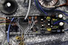
My Buffer Finally Done
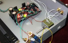
Here it is....
It took a bit long time to find closest voltage of LED (finally i found around 1,8V LED, but then i realize that even i have all same voltage on LED, it won't give the same output voltage to supply the buffer because we dont match the transistor and other components, so we should compromise this by adjusting our LEDs. Therefore the LED voltage between positive and negative side isnt the same but resulting the same output voltage). The output voltage is about 10,7V - 0V - (-10,7V) with +/-0.05V ripple. Offset is about 0.7mV at positive voltage and 1.7mV at negative voltage.
I can feel more detail in sound. There are some resistors valued different from the schematic. They are:
37.4R 1W instead 34R 1W
464R instead 470R
215R instead 220R
Is this okay? Or is it degrade the sound quality from this buffer should offer actually?
Thank you all, especially for Salas the designer and crt as i use his file then modify it properly to fit the components i used.
Attachments

Last edited:
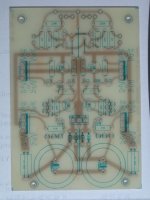
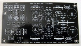
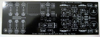
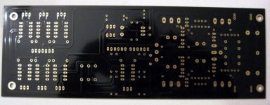
For those who don't follow the DCB1 group buy, the news are that Tea-Bag is the new GB manager. He has already given proto PCBs that Crt designed, out to several members and the protos are testing OK. He has opened a google document for everybody originally interested in boards to sign up. If we hit more than 100 pcs we are talking sub $10 per board. There are 2 options. The Hypnotize with only a delay relay on output for avoiding DC offset hick ups during on/off and it can be used as a one input buffer or augmented with a classic input switch, and Mezmerize, that sports 6 inputs via relays. Both need a 15-25k stereo log pot.
If you had your name on the original old wiki GB or new to it, sign up here:
http://spreadsheets.google.com/ccc?key=0An3nVM43ZbQndHJSMVNSLVBwbVFUSEh5cXI3WnpDRnc&hl=en
If you had your name on the original old wiki GB or new to it, sign up here:
http://spreadsheets.google.com/ccc?key=0An3nVM43ZbQndHJSMVNSLVBwbVFUSEh5cXI3WnpDRnc&hl=en
Attachments
5. Risks are: If you are not careful and there is no input capacitor in your power amplifier, or DC output sensor and relay, you can burn woofers, if you connect a source device with much DC offset, or one symmetric B1 supply fails during service. Be warned.
Does the above 'risk' still exist in this buffer?
Does the above 'risk' still exist in this buffer?
You can build a DC sensing / off set protection circuit - to avoid this problem. Power amps generally should have either a coupling Cap in most of the cases or should have a DC sensing /shut off system if it is DC coupled to the speaker.
kannan
- Home
- Amplifiers
- Pass Labs
- Building a symmetrical PSU B1 buffer