
Yes if you want them to show a long life without servicing needs. Same with semiconductors. Haven't you noticed how Papa over specifies power Mosfets in Class A amps? There they dissipate constantly enough like DC warmed up resistors.
P.S. Tell us more about your system configuration and what you replaced with DCB1, and the sonic footprint. Maybe even a picture if you may.
P.S. Tell us more about your system configuration and what you replaced with DCB1, and the sonic footprint. Maybe even a picture if you may.
Well, I'm not very well at listening, but I have noticed more punch and more defined bass tones. Especially in drums or in the slap of an upright bass. I haven't give it a serious listening yet, only while doing other things.
It is connected to a gainclone LM3886 with a regulated PSU. It's been made from carlosfm's schematics, both amp and PSU.
My source are not the best, mainly mp3 and cds, played on the PC through a modded EMU 0404USB, wich has been changed to better electrolytics caps. I still have to change the output opamps to better ones.
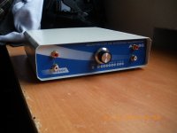
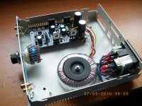
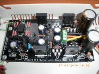
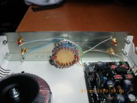
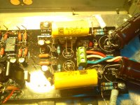
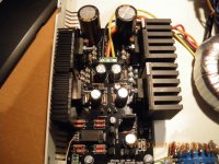
This is my DCB1. I dont plan to make it look better or painting it, my mainly end is trying to get best sound. I finished that DIY stepped attenuator last week, it's 20k. I found a bargain at ebay, a 24 steps double rotary switch for 10$ shippment included, so I had to bought the Dales from mouser. It is internal wired with single core cat5e wires. It has placed underneath an output cap for the delay-start regulator. Pannasonic FM and Nichicon Audio KW capacitors, Dale and Takeman resistors. An all-steel chassis construction.
It sounds excepcionaly clean, putting my ear near the cone at max vol I cannot hear even a slight hum from it. It was substituting nothing, I was controlling the volume with the pot of the emu0404. I plan to bypass it with a wire, it doesnt seem to be good enought for the task.
It is connected to a gainclone LM3886 with a regulated PSU. It's been made from carlosfm's schematics, both amp and PSU.
My source are not the best, mainly mp3 and cds, played on the PC through a modded EMU 0404USB, wich has been changed to better electrolytics caps. I still have to change the output opamps to better ones.
This is my DCB1. I dont plan to make it look better or painting it, my mainly end is trying to get best sound. I finished that DIY stepped attenuator last week, it's 20k. I found a bargain at ebay, a 24 steps double rotary switch for 10$ shippment included, so I had to bought the Dales from mouser. It is internal wired with single core cat5e wires. It has placed underneath an output cap for the delay-start regulator. Pannasonic FM and Nichicon Audio KW capacitors, Dale and Takeman resistors. An all-steel chassis construction.
It sounds excepcionaly clean, putting my ear near the cone at max vol I cannot hear even a slight hum from it. It was substituting nothing, I was controlling the volume with the pot of the emu0404. I plan to bypass it with a wire, it doesnt seem to be good enought for the task.
Attachments
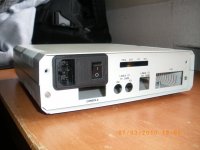

Yes its nice to see a shining one. Do short your Emu's output pot, will help. I see 3 gold flashed pins on the reg bus. You plan to supply something extra?
I don't plan to supply anything else, I just put those pins to work as test probes, to check voltages, etc.
I have another spare DCB1 board if in the future I plan another preamp or just the shunt supply to power anything like, maybe, a DAC. I haven't yet found a near perfect DAC which decided me to build. The same as this DCB1 or my PPAv2 headphone amp (which I consider both to be amongst the best devices in their class), I am still looking for a long term high end dac.
Tea-bag, could you post some photos of your construction? Maybe you did it before, but I can't remember seeing one with the whole chasis.
I replaced those 100uF caps with some film ones today, hoping to get a listen later tonight. On first turn on, its very subtle, but maybe its a little smoother than before, but I can't really tell yet.
The caps are from madisound, carli caps:
Carli Mylar 4.7 mfd from Madisound
I do have some Wima MKP 4.7uF (as well as much smaller values, 0.22 and 0.33uF) that I can swap in but they're not as easy to mount.
More later....
Fran
The caps are from madisound, carli caps:
Carli Mylar 4.7 mfd from Madisound
I do have some Wima MKP 4.7uF (as well as much smaller values, 0.22 and 0.33uF) that I can swap in but they're not as easy to mount.
More later....
Fran
Attachments
Listen later, let it bleed a bit. Hey, that's an original tweaking DIYer's DCB1.
LOL, that it is, that it is......
Stuff has been on and off it so much, I think I've tried nearly every suggestion made so far!!
Best thing is, it sounds great!
Fran
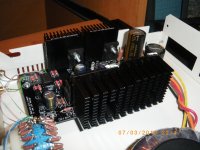
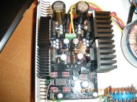
I'e been heatsinking it this evening, now it is ready for a big CCS.
What I have in my parts bin are 2W 2.2 Ohm, 2.7 Ohm and 4,7 Ohm.
I plan to put 2 x 4.7Ohm in series to achieve 9.4Ohm, what will give me (from 2.456v drop in R1) a 261mA CSS.
Or add a 3rd resistor of 2.2 in series to get 211mA CCS
With 261mA it disipates 0.64W and with 211 it does 0.5W. I think 2W resistors are enought for both options, what do you think?
Let's try to improve this baby!
Attachments
- Home
- Amplifiers
- Pass Labs
- Building a symmetrical PSU B1 buffer