Actually, it really makes no difference whether its in a separate case or not? In either way, its straight DC amp.
I've used the e12 as a muting delay in a headphone amp before, and found no sonic problems. Certainly would be worth it as an add on to this amp. Havn't used the DC protection part of it yet though - and I can't remember right now why I didn't......
Fran
I've used the e12 as a muting delay in a headphone amp before, and found no sonic problems. Certainly would be worth it as an add on to this amp. Havn't used the DC protection part of it yet though - and I can't remember right now why I didn't......
Fran
Ups the chance of more exposure to heat, something that turns more odds against prolonged failure free life. Everything in nature, the hotter it is the less it lives. Now, that would mean nothing in particular if there was some DC fault guard. You marry DCB1S & F5 especially in power's box, is like smoking at the gas station regarding long time parts failure leading to DC fault odds. Best for you is to put everything in same box, keeps interconnects out of the equation, BUT just use an output relay DC protection scheme, like the one Billy suggested. No coupling caps, short audio connections = ultimate transparency. Use an output guard and you can have your cake and eat it too. Simplistic thinking, don't you find?")
Not wanting to start a controversy here
I was just wondering.
My thought is that a buffer was used at the source end, so that
cable capacitance/inductance would be mitigated.
If I've already got a good buffer at the output of the source
component, why would I want to put another active component
at the input of the power amp? The B1 may be very transparent
but what is it's value at the amp end? In my, not so expert,
experience, removing passive/active devices in the signal
path has improved detail/resolution, with the proviso that
the source components output buffer is worthy.
The B1 may present a higher input impedence for the F5,
however the F5 already has a high input impedence.
What am I missing here?
It is not specifically designed for F5 AFAIK, this also counts for the Pass Labs B1. Please rad Nelson Pass writing about the B1 to see its merits.
http://www.passdiy.com/pdf/B1 Buffer Preamp.pdf
These versions are not original B1 buffers as they are DC coupled buffers without the input and output caps. So no sonical degradation from coupling caps.
They are high impedance in, low impedance out buffers to be used at the source end, so that cable capacitance/inductance will be mitigated. Try doing so with only a volume potentiometer with a long cable attached to it and you will know why an active buffer has its advantages.
Things become different when everything is built in just one case. In that case a buffer (generally) is not needed.
Last edited:
They are high impedance in, low impedance out buffers to be used at the source end, so that cable capacitance/inductance will be mitigated.
Exactly, that's what I wrote in my post,
"My thought is that a buffer was used at the source end, so that
cable capacitance/inductance would be mitigated."
I see the source as "a cd player etc. connected with short cables to a preamp/buffer".
This source-combination feeds longer cables to the power amp.
Amen.
In my config the dac, the ESS Sabre, has a digital vol. control and is
direct coupled to the power amp, an F5. No capacitors in the signal
path until the tweeter cap.
The Sabre can drive head phones directly, by that I mean the
output is up to the task of driving cables.
When I build up my Hypnotze B1 board I will place it after the
dac outputs and give it a listen. Either way I'll need it to buffer
a soon to come phono stage.
..... I've tried it both ways, and buffalo directly to F5 sounds excellent. You don't need a buffer in this app I think.
Fran
Thanks for the reply, I too find direct into the F5 very good.

So, the buffer will be used with the phono stage only.
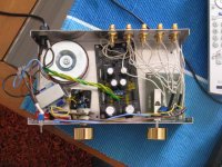
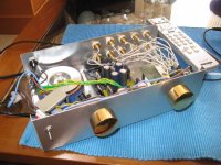
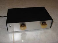
Just finished my symmetric B1.
Volume is controled by LDRs and it has three inputs and two outputs, one direct and one through the buffer.
Just want to thank everyone who helped so much here for this project.
Volume is controled by LDRs and it has three inputs and two outputs, one direct and one through the buffer.
Just want to thank everyone who helped so much here for this project.
Attachments
Just finished my symmetric B1.
Volume is controled by LDRs and it has three inputs and two outputs, one direct and one through the buffer.
Just want to thank everyone who helped so much here for this project.
Did you have a listen yet?Vgeorge,
Are you using the DCB1 just for power supply? It looks like the B1 portion of it is not fully populated. Maybe its just a pic before you finished. What is that little board on the right?
Uriah
I just haven' t implemented the relay part yet. It works fine without it, a little bit risky though.
The little board on the right for the input switch. The LDRs are located on top of it. They have a separate transformer and supply.
Not yet, as I still have to finish my speakers and doing renovation work on my house.
I am going to use on my other system in Athens, driving gainclones with my Sonus Faber Electa Amator speakers.
I guess you feed an amp with C input?
Until I do the relay, I will.
- Home
- Amplifiers
- Pass Labs
- Building a symmetrical PSU B1 buffer