Have two SA/1's with early frontend (no optical bias).
When I switch them on the heat up within 20 minutes as intended by the designer. Within the first minute they draw 2.0 Amps a piece from a stable 230 Volts AC line. Then when the heatsink is warm - 46 degrees Celcius - they settle within twenty minutes at 2.4 amps and then slowly they start to decrease their current intake to 1.3 amps after approx. an hour. I measure a biasvoltage over a the 1.3 Ohms emitters (40 total) between 60 and 65 mV. That's fine by me although it's good for 30 Watts Class A at 8 Ohms and not the 160 Watts as specified.
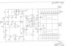
I ahve studied the schematic of the Series II frontend is this one is and found that there's a MPS6571 transistor connected to the biaspot and the NTC (Thermister) and that the temperature reaction of this VBE multiplier system is linear dependable of the B value of this transistor (hFE = min 250 - max 1000).
Somebody said I should replace this with a much more stable transistor like a MPSA06 with a hFE of 100 to have less biasdrift.
Question: Maybe somebody can explain it in simple terms to me with the schematic. I'm not a technician.
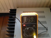
One of the amps get sometimes very hot when I'm playing music around the shift from Class A to B (30 Watts). I have thermal stickers placed at the coolingfins at the hottest place as near as possible to the chassis and the temperature raise above 50. I measured with a thermal rod and got 56 degrees. I immediately opened the amp, then even more current starts to flow because the inside temperature is decreasing and the NTC reacting, to adjust the bias. I measured 160 mV at one of the 1.3 Ohm emitters what means 5 amps of quiescent current is flowing through the amp. I turned it back to a more healthy figure of 70 mV and there it stayed. Happened twice within week.
I know there's a thermal cutout that will trip at 75 degrees Celcius but I reluctant to rely on that feature alone.
Any ideas why this has happened?
Beautiful sounding amp though, just as nice as the Levinson ML-2's I had for a couple of years but more power.
Thanks in advance
When I switch them on the heat up within 20 minutes as intended by the designer. Within the first minute they draw 2.0 Amps a piece from a stable 230 Volts AC line. Then when the heatsink is warm - 46 degrees Celcius - they settle within twenty minutes at 2.4 amps and then slowly they start to decrease their current intake to 1.3 amps after approx. an hour. I measure a biasvoltage over a the 1.3 Ohms emitters (40 total) between 60 and 65 mV. That's fine by me although it's good for 30 Watts Class A at 8 Ohms and not the 160 Watts as specified.
I ahve studied the schematic of the Series II frontend is this one is and found that there's a MPS6571 transistor connected to the biaspot and the NTC (Thermister) and that the temperature reaction of this VBE multiplier system is linear dependable of the B value of this transistor (hFE = min 250 - max 1000).
Somebody said I should replace this with a much more stable transistor like a MPSA06 with a hFE of 100 to have less biasdrift.
Question: Maybe somebody can explain it in simple terms to me with the schematic. I'm not a technician.
One of the amps get sometimes very hot when I'm playing music around the shift from Class A to B (30 Watts). I have thermal stickers placed at the coolingfins at the hottest place as near as possible to the chassis and the temperature raise above 50. I measured with a thermal rod and got 56 degrees. I immediately opened the amp, then even more current starts to flow because the inside temperature is decreasing and the NTC reacting, to adjust the bias. I measured 160 mV at one of the 1.3 Ohm emitters what means 5 amps of quiescent current is flowing through the amp. I turned it back to a more healthy figure of 70 mV and there it stayed. Happened twice within week.
I know there's a thermal cutout that will trip at 75 degrees Celcius but I reluctant to rely on that feature alone.
Any ideas why this has happened?
Beautiful sounding amp though, just as nice as the Levinson ML-2's I had for a couple of years but more power.
Thanks in advance
Attachments
Last edited by a moderator:
I'm not completely clear on this, but I think you might have a problem.
Each of the channels should be drawing about 350 watts or so with a bias
of roughly 3 amps. With 40 devices, that means a bias of 75 mA each or so.
I doubt that it's the 6571's, which have a very high beta, although it won't
hurt to replace them with a beta = 100 type device if you want to try it.
Assuming that both channels are doing this, I wonder if there is an issue
with the values of the thermistors. A logical way to experiment with this
is to try a lower value of resistor than the 1K already in parallel with the
thermistor and re-bias the amp.
In any case, you want the heat sink temperatures to be around 50 to 55
deg C and you want good ventilation for the amplifier.
Thanks for the response
According to the behaviour I described, what would be the expected response of the amp if I lowered the parallel fixed 1K resistor to let's say 250 Ohms?
When the thermistor (has it a negative temperature coëfficient, it's a NTC if I'm right?) is not good, what will happen then?
If it's okay would there be a different reaction?
How does the thermistor get's it's value, it is not poking into the aluminum heatsinks like the thermal cutout. Is it just ambient temperature? The optical bias version has I believe a thermistor poking into the heatsink.
The 3 Amps you describe, how can they lead to 160 Watts of Class A at 8 Ohms for a SA/1? It is only sufficient for 72 Watts to my knowledge. Not that I really care much as I already stated but it should be 4.5 Amps for 160 Watts. I've read a couple of interesting white papers from your hand on this matter of biasing and with illuminating graphs, you stress the point that enriching the amp with lots of biascurrent makes it's behaviour more liniar, meaning less distortion better sound. Just curiousity want my amp to behave proper as intended.
It's just ambient temperature. The supposition is that the thermistor is
adding too much compensation in this case, and reducing the 1K resistor
to something like 470 would about halve that.
Again, I am presuming that the amplifier is well ventilated in a room at about
25 deg C. If not, then we should address that first.
adding too much compensation in this case, and reducing the 1K resistor
to something like 470 would about halve that.
Again, I am presuming that the amplifier is well ventilated in a room at about
25 deg C. If not, then we should address that first.
I will try that solution.
The amplifiers are complete free standing on a wooden floor with an ambient roomtemperature between 20 - 22 degrees Celcius.
I can monitor temperature, emitterbias and AC intake at the same time.
The white radiator on the added picture is off, took the photo when the amp was still getting hotter to 56 Celcius.
Attachments
If that's the case, and bear in mind I could hardly touch the heatsinks, then the 160 Watts Class A at 8 Ohms would be a valid claim ;-)
Martin Colloms reviewer from Hifi News & Record Review and Stereophile and like it seems Krell fan forever and ever, always disputes theClass A claims in complementary pushpull designs.
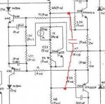
Marcel Croese from Prima Luna (he designed a new autobias-topology), former chief engineer with Goldmund SA, asked if there shouldn't be a .01 uF capacitor over the biasmotor (see picture) to keep the distortionlevel flat with rising frequencies?
Lat me say at last that I'm very pleased to communicate with a designer who displays such an involvement with his former designs. Maybe it's the aftercare that counts in the long run and it justifies the sacrifices in terms of alternative spending when enquiring this kind of equipment. Just a thought...
Martin Colloms reviewer from Hifi News & Record Review and Stereophile and like it seems Krell fan forever and ever, always disputes theClass A claims in complementary pushpull designs.
Marcel Croese from Prima Luna (he designed a new autobias-topology), former chief engineer with Goldmund SA, asked if there shouldn't be a .01 uF capacitor over the biasmotor (see picture) to keep the distortionlevel flat with rising frequencies?
Lat me say at last that I'm very pleased to communicate with a designer who displays such an involvement with his former designs. Maybe it's the aftercare that counts in the long run and it justifies the sacrifices in terms of alternative spending when enquiring this kind of equipment. Just a thought...
Attachments
Okay, When I can get the bias stable I'll try your resistor lowering advice first.
Sad I can't get the Heinemann circuitbreaker and the Modutec VU meter anymore. One of the Heinemans trips occasionally when I switch the amp on and the meters need some zero-adjusting, nothing really serious though.
Ordered 8 New old stock Cornell Dubiliers. 82.000 uF 75 V. I will reform them and put them in to replace the 25 year old Mallory's.
Thank you for all the advice.
Blown rialfuses
Just blew the 8A railfuses of my amp.
This channel started from the beginning with problems:
Heinemann Circuitbreaker tripped always immediately after a cold startup.
Probably one or a couple of the powertransitors (MJ15025 for PNP, and MJ15024 for NPN??) are gone.
The modutec meter stayed halfway the scale probably due to the caps decharging very slowly on the output after the transistorfailures.
Just before blewing the fuses I measured on a particulary emmitorresistor a thee times as hihg value as the other.
Should I find the broken transistor should I replace the complementery paired one as well?
Only the Stasis ones are Beta matched I believe
Any help or suggestions.
Thanks
It is quite rare to encounter such a level of mismatch between parallel
bipolars as the Vbe is quite consistent without matching. Matching simply
means selecting for high beta (current gain) for low distortion. It may
be that the resistor in question had been toasted to a higher value or that
the transistor was experiencing some sort of failure.
If you can obtain the same part numbers, I would simply replace the broken
parts and try again. Get a Variac - you will need it.
Well, the amps are already 25 years in service so a failure may be expected after such a time.
When I got the amps they both had a biasvalue measured over several emittors of 6 mV. That was way to low the amp only became 30 degrees Celcius warm. After turning up the bias problems maybe emerged after the amp got stressed a bit more.
Luckily my Acoustats were also protected with a 5 amp fuse that did blow also.
In Europe we expect that all American 19 inch highend equipment, that looks to be built to last forever, you don't expect a failure of this magnitude.
I just have to find the time to correct this problem.
Thanks for the support though.
Found this Threshold spec on this forum about biasing values fort all the Threshold amps kindly supplied by member R-K Rønningstad. Plus the comlete procedure how to bias the amp wit graphs and sequential instructions:
http://www.diyaudio.com/forums/showthread.php?s=&threadid=55055&highlight=mj15025+Threshold
Wish I had it before...
It specifies for the non opticalbias versionof the SA/1 and the S/1000 to by the way only 42 degrees Centigrade final value after a one hour warmup.
The temperature rod should be in the last hole from the back of the amp.
I learn in the proces....
Can't open the amp where I needed because do not have the right American 1/8 Inch hexagonal wrench that's long enough to get one section of the heatsink of so I can't find out what kind of NPN/PNP powertransistors this amp uses.
Probably paired ML15024/25 but I'm not sure.
Anybody knows for sure?
'member djk' suggested to replace them all (40) but I'm reluctant for obvious reasons to perform such an action.
I'm inclined to let a skilled technician who also is the Krell technician for the Netherlands to do this job but I'm willing to give it a try to get more hands on experience with this kind of work and it's rewarding when it succeeds. So I ordered a Variac and I give it a go.
Any last hints?
Attachments
- Status
- This old topic is closed. If you want to reopen this topic, contact a moderator using the "Report Post" button.
- Home
- Amplifiers
- Pass Labs
- Bias problems in Threshold SA/1