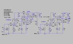
Lately there has been quite a few threads covering the work of OH Schade 1938, http://www.clarisonus.com/Archives/TubeTheory/Schade 1938 Beam Power Tubes.pdf . He showed how a tetrode could get triode characteristics with the help of what he called "inverse-voltage feedback". While working as a triode the efficiency of the tetrode was still kept.
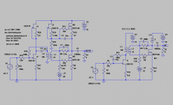
On the left is a tube SE in accordance to his suggestion. It has the same output impedance and distortion characteristics as if it had been triode-strapped but twice the output power! On the right the output device is substituted by a common MOSFET that according to Schades suggestion is feedbacked ca 20dB.
Seeing any similarity with a Zen ?
?
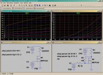
By the use of an IT there is a better chance of getting much better HF-bandwith. The example sims with a -3dB point in the region of 100kHz.
On the left is a tube SE in accordance to his suggestion. It has the same output impedance and distortion characteristics as if it had been triode-strapped but twice the output power! On the right the output device is substituted by a common MOSFET that according to Schades suggestion is feedbacked ca 20dB.
Seeing any similarity with a Zen
?By the use of an IT there is a better chance of getting much better HF-bandwith. The example sims with a -3dB point in the region of 100kHz.
Attachments
Let´s Schade the 2SK170
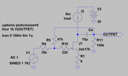
So what happens if we adapt what Schade taught us to a JFET as buffer?
Works like wonders !
Zout below 200ohms, together with low THD and acceptable bandwith (-3dB at well over 200kHz). Zin chosen to 10kohm. With 22kohm/91k bandwith is 100kHz.
But don´t try to a volume-pot at the input! Must be fed from a lowZ source.
So what happens if we adapt what Schade taught us to a JFET as buffer?
Works like wonders
! Zout below 200ohms, together with low THD and acceptable bandwith (-3dB at well over 200kHz). Zin chosen to 10kohm. With 22kohm/91k bandwith is 100kHz.
But don´t try to a volume-pot at the input! Must be fed from a lowZ source.
Attachments
but off course it inverts phase
Is this a problem? If so, just shift plus and minus on your speaker terminals
.Re: Let´s Schade the 2SK170
You don't need R10. This circuit works to provide a virtual ground at the
Gate of the JFET, so the input Z is 10 Kohm as shown. Actually you can drive
it with a range of source impedances, and adding a pot as high as 25K should
work fine.
revintage said:Zout below 200ohms, together with low THD and acceptable bandwith (-3dB at well over 200kHz). Zin chosen to 10kohm. With 22kohm/91k bandwith is 100kHz.
But don´t try to a volume-pot at the input! Must be fed from a lowZ source.
You don't need R10. This circuit works to provide a virtual ground at the
Gate of the JFET, so the input Z is 10 Kohm as shown. Actually you can drive
it with a range of source impedances, and adding a pot as high as 25K should
work fine.
HighZ lowZ, don't matter. As long as its stable with frequency.
It just becomes part of the feedback divider...
There's a nice photo of a curve trace for a similar circuit:
www.radiomuseum.org/forum/the_trioderizer_a_solid_state_triode.htm
The only difference, Trioderizer gate is battery biased.
A battery could last a long time, if its only biasing gate...
I imagine you would want to bypass with a good cap???
something weird with that link. You have to find it the hard way...
Forum »
Technique, Repair, Restaurtion, Home construction ** »
Home construction and general radio technique »
The Trioderizer - a solid state triode
Nelson: The 220 was a remain from the MOSFET simulation and is not needed here.
About the volume pot, it works a little bit different as it becomes a part of the of the feedback circuit. Probably another log curve will be needed.
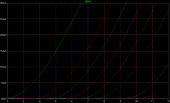
Below is a Spice sim of the circuit above. 2SK170 10k/47k NFB. Looks like a decent triode.
About the volume pot, it works a little bit different as it becomes a part of the of the feedback circuit. Probably another log curve will be needed.
Below is a Spice sim of the circuit above. 2SK170 10k/47k NFB. Looks like a decent triode
.Attachments
What about a "Schaded" JFET as driver to a "Schaded" MOSFET SE?
The left one with a combined gyrator and CVS(Constant Voltage Source) instead of choke. As no current goes through the transformer in the left example a LL1676 2:1 could be used.
Thought some more about a volume-control before the buffer:
With a 10k pot Zin will vary from 5k to 10kohm.
With a 20k pot Zin will vary from 7k to 25kohm,
So the 22k/91k network will be better as a 20k pot will give us from just above 10k(fully open) to 20kohm(closed).
Attachments
You may have designed out the best feature of Zen and Triodes.
That local voltage linearizing feedback be entirely direct coupled.
It doesn't get any more direct coupled than the intrisic space
charge gradient of the Triode. But enhancement MOSFET Zen
comes awful close... Only reactive component the gate itself.
While I hear rumour said capacitance tends to be nonlinear,
its probably less an issue than microphonics in a glass Triode.
I'm not sure transformer coupling is adequately modeled by
LTSpice? Nor am I convincved that throwing a drain cap into
the loop is the best solution. I'm thinking direct coupled JFET
Zen might be the answer, with a depletion mode bias offest
provided by a constant current. No reactive shifts anywhere
in the Schade network.
That constant current, need not be "constant". It could be
the drain of an active JFET (or cascode of JFETs) with an
unbypassed source resistor. That provides a linear voltage
controlled current of high impedance, to tickle the Schaded
JFET stage into action. Tickle currents becoming voltages
again, within the Schade network's resistors.
------------------------------------------
And a glass Triode's 1/(Mu-1) from Plate to Cathode can be
stand-in for Zen's resistive network, to linearize a MOSFET.
Our device then also benefits of the triode's grid for input
buffer. Same glass Mu Schading trick works equally well for
Bipolar transistors too, Oldie's Triodlington...
I've drawn somewhere around here at least once before,
Zenlington. Like Triodlington. Very tiny signal MOSFET of
enhancement mode, voltage linearized by Zen/Schade.
Then boosted in current by Beta/Darlington.
Kenpeter,
The transformer sims are pretty basic so IRL tests will show how compensation should be done. But comparision shows that this way you get better HF-response.
About direct-coupling between the stages this is a NONO as the 2SK170 will not be capable of driving a 1,5k load. Instead of a CF/SF, the transformer will be much better sounding impedance-converter.
It is soon time for a IRL test of my theories. The Hammond 193U´s are ordered and a 24V PSU is also on its way. Chassis, LL1676´s and heatsinks are already in stock.
I had initially calculated for 18V/1,5A for the output device but sims are a lot better with 24V/1,5A but for the unsymmetric clipping. It is thought to be used as a 5-8W amp.
I had initially calculated for 18V/1,5A for the output device but sims are a lot better with 24V/1,5A but for the unsymmetric clipping. It is thought to be used as a 5-8W amp.
An externally hosted image should be here but it was not working when we last tested it.
I guess, that the M100A (M 100 A, M100) from "Esoteric Audio Research" (EAR, Tim Paravicini) could be a commercial product with similar circuit topology inside - please go to the weblinks
http://www.stoneaudio.co.uk/
http://www.savantaudio.com/earm100.html
http://www.enjoythemusic.com/SuperiorAudio/equipment/1206/ear_yoshino_834t.htm
http://www.envogue-24.de/Neue Seiten/ear/M100A.html
the detailed description is to find by the last weblink, but only in German
perhaps anybody has a detailled schematic diagram and photos from inside of this power OT-SE power amplifier
Quote from
http://www.enjoythemusic.com/magazine/equipment/0301/daveglakin2001ces.htm
The Best Un-Solid-State-Like Solid State Electronics (Tie) were from Tim deParavicini of Esoteric Audio Research. Tim was demonstrating the M100 A single-ended solid-state Class A transformer-coupled 100W monoblock power amps with his model 312 solid state transformer-coupled preamp ($35,000 and $18,000, respectively). Speakers were the Kharma Ceramic 1 Limited Edition. Solid state is quite a departure for Tim, but the beautiful sound that he was getting spoke for itself. It didn't sound like solid state or tubes, but it did sound an awful lot like music. You can contact E.A.R. USA via phone at (562) 422-4747 or via fax at (562) 422-6577 in Long Beach, California. (That's so retro.) You'll find Kharma at www.kharmausa.com.
Quote from
http://www.scribd.com/doc/7199629/Paravicini-M100A-Twin-Tower2
Paravicini M100A First Solid State Single Ended Power Amplifier The M100 monoblock power amplifier, EAR/Yoshino’s second venture into solid state. Tim de Paravicini has burned the rulebook as usual, producing a pure Class A, single ended, 100W monster which combines awesome sonic authority with exquisite filigree detail. Unique circuit design - including one of Tim’s legendary output transformers - ensures the perfect match between the traditional audio virtues of valves and transistors. Superb construction, great looks, novel heatsinks (no perilous sharp edges - and no noisy fans!), high reliability, extraordinary pride of ownership. Discerning audiophiles prepared to lose some serious weight in the wallet department will need little persuading. Specifications Maximum output: Frequency response (at 1W output): Power bandwidth: Input impedance: Damping factor: Sensitivity: Residual noise (volume at minimum): Distortion: Max. Size (overall, excluding control knobs): Weight (nett): 100W (28VRMS on 8 ohm terminals) -3dB at 3Hz, 40kHz -3dB at 20Hz, 40kHz 47kohm 8 1V for full output 0.5mV 2% at full power W 240mm, D 500mm, H 570mm 70kg Yoshino Ltd. Coombe Grove Farm, Ermine Way, Arrington, Cambs. SG8 0AL Tel No. +44 (0) 1223 208877, Fax No. +44 (0) 1223 208761
Last edited:
- Home
- Amplifiers
- Pass Labs
- O.H. Schade (1938) meets mosFET