Hi Folks
Finally with a lot of help from a number of people on this board, I turned up a single channel of the Zen V4 with a 1.5Amp fuse and 110V AC straight. I unfortunately did not have a variac (maybe I should buy one now).
I checked that the transistors have been heatsinked properly and that the drains are not grounded in any way.
I had R4 set all the way counter-clockwise.
1. Noticed that the 1.5 Amp slow blow fuse blew.
2. I increased the fuse to 3.0 Amp slow blow and tried it again.
3. In about 10 seconds I could see some smoke coming from the PCB.
4. On close examination I found that the problem is to do with the R0 and R1 resistors. They are blown.
5. This seems similar to
Jag's Problem
I am using the exact components (even the transistors) mentioned by Pass in his article and also his PCB. I also had a probe on the 25000uF power supply capacitor and noticed that the voltage was about 50V before the resistors blew.
Is there any way I can check if the transistors have blown without removing them from the board or do I need to remove them and check them. I cant seem to see anything on visual examination, but I will look at them closely.
Any help will be appreciated
thanks
vsr
when i had this problem http://www.diyaudio.com/forums/showthread.php?postid=83489#post83489
i took the fets out for testing. When Q1 and /or Q2 are taken away from pcb you should be able to test only the regulator for funktion. when there is Q1 away you should be able to test the current source with a resitor / lightbulb etc. I needed some resistores for R0 / R1 until i got it right. I used only one resistor here for start, 1R, then, to have lower bias. (things get hot slowly so)
The best would be to use a variac. I had oscillation problems with bad wires from power supply to PCB. Don´t use Crocos or so, use thick enough and soliered wires.
Light bulb is your friend
Most probably your Qs are blown. The best course of action I can recommend is to replace Q1, Q2, Q5 and try again. Also, never put a 3 amp fuse - sure way to get stuff fried
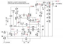
Once the Qs have been replaced, put a 150W bulb in series with your primary. You should see following voltages (in red). Any deviations will tell you what the problem is (without causing further damage):
Most probably your Qs are blown. The best course of action I can recommend is to replace Q1, Q2, Q5 and try again. Also, never put a 3 amp fuse - sure way to get stuff fried
Once the Qs have been replaced, put a 150W bulb in series with your primary. You should see following voltages (in red). Any deviations will tell you what the problem is (without causing further damage):
Attachments
thanks for your replies, heres what I plan to do next -
1. Replace Q1, Q2 and Q5 (my assumption is that they dont need to be matched). Any suggestions on whether I should replace this with the same transistors as in the Q pack or whether I should go with all 044 devices? or the same as what came with the Q pack? Right now I have one 044 (Q1) and 2 240 devices (Q2 and Q5).
Jag, you mentioned to not go with the 3 amp fuse, should I just stick to the 1.5 amp fuse then? Also I was reading your thread but couldnt find the reason why the Resistors R0 and R1 blew. What did you do wrong? It could be that I have the same problem.
2. Put the 150W bulb in series with the primary and try again or I will probably get a variac, I saw one for a reasonable price in a local surplus store. How much should my output of the variac be to mimick the 150W bulb, is it approx 75 v input?
3. I will check for the voltages and see which ones dont match.
thanks
vsr
Voltage across R0and R1 is what smoked them.
The very low resistance values of the R0 and R1. The problem is if the volatge raises above the normal 0.66v. With the resistance at 0.33 ohms for the pair, running just 2 volts will put six amps through. With this you are running 6 x 6 x 0.33 or 12 watts.
The 2 volts was just a number, you could have a much higher voltage.
George
- Status
- This old topic is closed. If you want to reopen this topic, contact a moderator using the "Report Post" button.