I have read Pass's article on grounding many times and I do not have an advanced understanding of electronics only a basic knowledge, but I am still not clear about the notion of grounding.
It appears to be a very complicated topic as was once said to me by an audio designer.
Right. I'm going to state my current understanding and start to ask questions about things I'm not clear about.
1) In an electric circuit, we can have plus, minus or a centre tapped zero point and a plus and minus. This is so that current can flow from plus to minus. However, often, the minus is also shown as ground on the circuit diagram. What does that mean?
2) I have never understood how a ground loop works despite reading up on it dozens of times. My understanding is that a ground loop is nothing but a differential in potential which causes current to flow. Where and how does this potential difference arise?
1) Not much. It's just terminology.
2) This is the much more interesting question. Most of the answer lies in the fact that no conductor has zero resistance. Any current flowing will produce a voltage across the conductor. From that you can see that if you call a certain point "ground" and declare that it has a potential of 0.000000000 volts, no other so-called ground will be at the same voltage (zero) if any current is flowing. In general, you want to arrange ground paths such that the inevitable voltages that are generated across the conductors don't affect other parts of the circuit. This is the logic behind the "single point ground", where separate conductors take the currents back to the defined ground point. SGP doesn't solve all problems though.
Currents flow because a potential has been applied to the circuit, but once you're looking at the details of a circuit, it's more useful to look at it the other way 'round. Current *is* flowing, and conductors have resistance, so what potential differences are generated locally?
I don't find the term "ground loop" all that enlightening as I think it means different things to different people. I just go back to the above application of Ohm's law, and try to think about what happens not only at DC and low frequencies, but at HF as well.
2) I'm not sure I follow what youre saying. I agree that any conductor will have a small resistance. But if we pick 2 points on that conductor why should they be at different potentials?
Two other questions also:
3) In that article by Pass, it states to keep all the length of wires to the single ground point of equal length. But how would this be possible given that the wires all originate from various parts in the circuit? For example one wire might be from the power transformer in which case the wire is as long as the coil. Another wire might originate from the negative rail of the speaker output (say on an amplifier) in which case again, the length is arguably the length of the loudspeaker cable and even the coil and so on.
4.) The article also states that we should not swap neutral and live since the fuse would then also be swapped. My understanding is that the mains supply is to all intents a symmetrical supply, roughly that of a sin wave which we know is periodic and so should not make any difference which way we plug it in?
Hi Conrad and Professor,
My 2 cents, most everybody uses the term ground incorrectly, and that does cause confusion for many DIYers, I believe. To really get a firm grasp you must go back to the way the utility power grid is set up.
Entering your house are 2 hot wires, a neutral, and a ground. In your electrical panel the neutral and ground are tied together, but this still does not make the neutral a ground point. That is why you still have 3 prong outlets throughout your house. The neutral carries the return current back to your power source, just as the DC PS common, or center tap, or minus point in a single supply, carries the return current back to the power supply.
When a lot of diyers lay out their chassis wiring they confuse the roles that parts of their wiring scheme must play. For instance, in a power amp chassis you would not want the return path from the output circuitry sharing the return path from the front end circuitry unless that is inherent in the circuit design for various reasons.
When I lay out a scheme I ignore any thought of grounding anything, I work at returning the circuitry to the PS in as direct a way as possible. The barrel of an RCA connecter is not a ground unless you choose to make it so, it is a signal return path that should be run to the appropriate point in the signal circuitry, not grounded to the chassis, which plays no part in the circuit operation.
I think if we choose to continue to call these points grounds then we should separate them by calling them PS grounds, signal grounds, and chassis grounds, because they are all different.
Enough ranting from me, I know I'll get arguments from someone, but my approach has worked for me for many years.:grin:
Bill
you live in the UK.Professor smith said:4.) The article also states that we should not swap neutral and live since the fuse would then also be swapped. My understanding is that the mains supply is to all intents a symmetrical supply, roughly that of a sin wave which we know is periodic and so should not make any difference which way we plug it in?
You must have grown up and survived by knowing one must never swap Live and Neutral. We even have polarised socket outlets and polarised plug tops to ensure we cannot insert the plug top inverted.
I agree completely, each return should be associated with it's source/flow.Bill Fuss said:most everybody uses the term ground incorrectly, and that does cause confusion for many DIYers, ...............
The barrel of an RCA connecter is not a ground ............. it is a signal return path that should be run to the appropriate point in the signal circuitry, ....................
we should separate them by calling them PS grounds, signal grounds, and chassis grounds, because they are all different.
We should start the change here by always being unambiguous when calling up a specific return by it's proper and definitive name.
eg.
Safety Earth is not a ground.
Mains Neutral is not a ground.
Chassis is not a ground.
Be specific, always.
Professor smith said:anybody else willing to respond?
If you ask new questions, then sure yes, but your initial questions has been answered, no?
Magura
")
well no actually people come in here and divert attention.
I dont mind that but it is my topic and I do want my questions to be asnwered. The other thing which I commented on previosuly is that if I ask a question, someone responds then I ask another and somebody else responds. This can be very confusing for me because I cant have more than 1 conversation at once.
So let me post up what i said again:
2) I'm not sure I follow what youre saying. I agree that any conductor will have a small resistance. But if we pick 2 points on that conductor why should they be at different potentials?
Two other questions also:
3) In that article by Pass, it states to keep all the length of wires to the single ground point of equal length. But how would this be possible given that the wires all originate from various parts in the circuit? For example one wire might be from the power transformer in which case the wire is as long as the coil. Another wire might originate from the negative rail of the speaker output (say on an amplifier) in which case again, the length is arguably the length of the loudspeaker cable and even the coil and so on.
4.) The article also states that we should not swap neutral and live since the fuse would then also be swapped. My understanding is that the mains supply is to all intents a symmetrical supply, roughly that of a sin wave which we know is periodic and so should not make any difference which way we plug it in?
Actually Professor, I replied before your last post so I didn't see it.
2) if there is current flow through a conductor there will be a difference in potential from any point to any other point. It all depends on the amount of current, the conductor size, and the distance. If you mix a large current flow with a small one using the same path you will modulate {for lack of a better word] the lesser signal, or whatever you want to call it.
3)I agree it's impossible to keep all paths even remotely equal, I'm not sure what point NP was trying to make. I'm not familiar with the article to be truthful.
4)It's true the secondary side of the transformer doesn't care how the primaries are fed, but if you switch or fuse the neutral all the primary circuitry will be live all the time, kinda dangerous, don't you think.
I've found that most hum problems end up being ground loops that are very difficult to see beforehand and sometimes take trial and error to eliminate, regardless of someone's theoretical knowledge.
Bill
Bill Fuss said:Actually Professor, I replied before your last post so I didn't see it.
2) if there is current flow through a conductor there will be a difference in potential from any point to any other point. It all depends on the amount of current, the conductor size, and the distance. If you mix a large current flow with a small one using the same path you will modulate {for lack of a better word] the lesser signal, or whatever you want to call it.
3)I agree it's impossible to keep all paths even remotely equal, I'm not sure what point NP was trying to make. I'm not familiar with the article to be truthful.
4)It's true the secondary side of the transformer doesn't care how the primaries are fed, but if you switch or fuse the neutral all the primary circuitry will be live all the time, kinda dangerous, don't you think.
I've found that most hum problems end up being ground loops that are very difficult to see beforehand and sometimes take trial and error to eliminate, regardless of someone's theoretical knowledge.
Bill
2) yes however that's precisely my question. WHY should there be current flowing? I dont get that. Just to be clear, we are considering a piece of metal yes? and we are saying that there is a current flow between any two points? Thats curious.
4) I still dont get why we shouldnt swap them. Please explain to me. My understanding is that Live and neutral are just names for two arbitrary points.
Professor smith said:
2) I'm not sure I follow what youre saying. I agree that any conductor will have a small resistance. But if we pick 2 points on that conductor why should they be at different potentials?
If an electron leaves "one point", travels the electronic circuits here and there and comes back to "that point", I would say that "that point" is the ground point (chosen as zero electrical potential).
My pre amp has its own that point (A-ground point). And, my power amp has its own that point (B-ground point). But, when these two independent equipments are connected into one system, I have to choose one of A- or B-ground point as its own "that point". For example, if I choose A-ground point as "that point", B-ground point is no more actual ground point. If so, there could be electrical potential generated between A-ground point and B-ground point because the electron leaving "that point" (A-ground point) might travel preamp and power amp circuits and comes back to "that point" (A-ground point).
Sorry, I'm talking too much bla bla . . . In the early morning, my tongue is fairly fresh . . .
>
<Professor smith said:1) In an electric circuit, we can have plus, minus or a centre tapped zero point and a plus and minus. This is so that current can flow from plus to minus. However, often, the minus is also shown as ground on the circuit diagram. What does that mean?
Nothing. It doesn't signify sh1t.
This is a holy mystery, insight into which is granted only to the few.
Ground is significant because the planet is a conductor. This makes a difference at radio frequencies, in, for example, the radiation patterns of antennas. Thus you get single ended installations (vertical monopoles) and balanced antennas (dipoles), it's not just something arbitrary invented by some nitpicking engineer.
Professor smith said:2) I have never understood how a ground loop works despite reading up on it dozens of times. My understanding is that a ground loop is nothing but a differential in potential which causes current to flow. Where and how does this potential difference arise?
This is totally 4ss-backwards. It's because the currents flow that the potentials develop. Each active component returns current to the supply. You have to look at where the return currents actually GO. Locally. Then you understand why they cause problems, because of the unwanted differences in potential that develop.
w
Professor smith said:
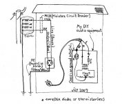
4) I still dont get why we shouldnt swap them. Please explain to me. My understanding is that Live and neutral are just names for two arbitrary points.
I hope this will help . . .
Attachments
Babowana said:
I hope this will help . . .
But i still dont get it. I understand the picture you've drawn but if you touch either one of live or neutral you will get a big shock no?
I dont see why one would give you a shock when the other wont. In fact I did an experiment once where I touched only ONE of the points and I received avery heavy shock. My thumb turned black. However why did I get a shock by touching only 1 point?
Circuit theory tells us that current flows between TWO points. Only my thumb made contact.
Re: Re: The grounding
Ohms law tells us that in any closed circuit with V,I, and R
I= V/R or equivalently V=RI.
Both equations are equivalent so it doesnt' tell us anything about which way is forwards or backwards.
wakibaki said:
Nothing. It doesn't signify sh1t.
This is a holy mystery, insight into which is granted only to the few.
Ground is significant because the planet is a conductor. This makes a difference at radio frequencies, in, for example, the radiation patterns of antennas. Thus you get single ended installations (vertical monopoles) and balanced antennas (dipoles), it's not just something arbitrary invented by some nitpicking engineer.
This is totally 4ss-backwards. It's because the currents flow that the potentials develop. Each active component returns current to the supply. You have to look at where the return currents actually GO. Locally. Then you understand why they cause problems, because of the unwanted differences in potential that develop.
w
Ohms law tells us that in any closed circuit with V,I, and R
I= V/R or equivalently V=RI.
Both equations are equivalent so it doesnt' tell us anything about which way is forwards or backwards.
My point is that if we have a battery and a resistor, this gives us our V and R respectively. We can now determine I using ohms law.
Resistance is a natural property the existence of which we can presuppose.
In what sense can we pressupose the existence of current in a piece of metal conductor?
Resistance is a natural property the existence of which we can presuppose.
In what sense can we pressupose the existence of current in a piece of metal conductor?
Professor smith said:My thumb turned black.
...
...
Only my thumb made contact.
Since the theory is correct you must be mistaken. Your thumb did not turn black. Why not repeat the experiment with other parts of your body and report back?
w
- Status
- This old topic is closed. If you want to reopen this topic, contact a moderator using the "Report Post" button.
- Home
- Amplifiers
- Pass Labs
- The grounding