So after about six weeks listening to my F5 I'm still very happy with it, but of course I'm now ready for another project. (I've done a Le Monstre (re)build in the meantime, which also worked out well with the help of the good folks on the solid state forum). I've been thinking about doing a preamp to complement the F5, but I'm also fascinated by the idea of another F-series, and I find myself with more questions.... So here they are...
1. I have read a fair bit about the F4, although I confess that I haven't ploughed my way through all 117 pages of the big F4 thread... I also took a look at the F1. If I understand correctly, the F4 provides no gain, in the sense that the output voltage is (more or less) the same as the input voltage; it is an amplifier in the sense that output current is greater than input current. Am I right in thinking that it does this since its output impedance is much lower than input impedance, hence the same voltage gives more current? If so, is it (at least approximately) correct to think of it as basically doing the same thing as B1 buffer, just much bigger?
2. Has anyone used an F4 *following* an F5 or a Le Monstre? What would be the effect? I presume the F4 makes the sound louder, at least in some sense, or it wouldn't be an amplfier, right? (Or have I misunderstood...?) If the Monstre gives enough volume in my (very small) home office through my FE127e's, is there any benefit to using an F4? How about just a B1 followed by the F4? (In principle I can build it and try these combinations out, of course, but it isn't a cheap thing to build, so I'd like some kind of idea to help with decision-making...)
3. I have tried my F5 in my (quite large) living room (feeding B&W CDM2's, about 87 dB/W, I believe, so not particularly efficient) and it provides plenty of volume for what I need, although hard rock fans might think it a bit quiet, I suppose. I have tried it with the B1 preamp I made, and with a commercial Creek preamp (P43 from some time on the 90's). Best is the B1, but I'm using that in my office, so it's the Creek for the time being, but replacing it with something diy is a no-brainer.... I am interested in doing another B1 (and spending a little $$$ on it, rather than the bargain-basement version I did last time...) but it seems a lost opportunity to try something different. So, I wondered about doing a B1 with a gain stage which could be switched in or out. (Possibly simply using different output RCAs for gain/ no gain rather than an actual switch...) The obvious candidate would be a B3, when Nelson makes the circuit available, but can anyone (Nelson?) confirm that it's a gain stage after a B1 circuit? Or is it totally different? Does this idea even make any sense? I'm even tempted to have a first try at a tube circuit, and do a B1 with some sort of tube gain stage.... hhmmmmm... Suggestions?
Well, I'm grateful for any answers/comments...
Cheers
Nigel
1) The F4 does not deliver voltage gain, but it does have lots and lots
of current gain. Just about anything that can deliver the voltage will
be happy with it. Yes, it's a very large buffer.
2) An F4 will be happy following just about any power amp, but
keep in mind that it will not follow above 20V peak (50 watt @ 8 ohms
peak). Keep in mind that it has to be driven by the active output
terminal, which is the red on most, but not all, amps.
3) Last time I looked, the B3 was a gain stage following a volume
control. I have not yet decided to release the circuit as a DIY
project at this time. Maybe you would like to try the Impasse
preamp.
Nelson Pass said:1) The F4 does not deliver voltage gain, but it does have lots and lots
of current gain. Just about anything that can deliver the voltage will
be happy with it. Yes, it's a very large buffer.
2) An F4 will be happy following just about any power amp, but
keep in mind that it will not follow above 20V peak (50 watt @ 8 ohms
peak). Keep in mind that it has to be driven by the active output
terminal, which is the red on most, but not all, amps.
3) Last time I looked, the B3 was a gain stage following a volume
control. I have not yet decided to release the circuit as a DIY
project at this time. Maybe you would like to try the Impasse
preamp.
OK, thanks Nelson. I'll do a search and take a look at the Impasse preamp. Definitely interested in the F4, though.... I'm fascinated to listen to one, and the only way I'm going to hear one is to make one....
Cheers
Nigel
I did the tour of car audio repair places this morning in search of heatsinks, and came back with two large-ish ones from burned-out power modules, although not a matching pair. These could be cut up with a hacksaw and reassembled (Frankenstein-like) for use in an amp, but the total surface area (anodized alu.) is between 1/2 and 2/3 of what I used on the F5. This tells me they are not sufficient for a full-blown F4, but would certainly be adequate for some smaller-scale amp. (Please bear in mind that buying proper heatsinks here is very expensive... otherwise I wouldn't be doing things this way...)
So I was wondering about a scaled-down version of the F4. On Post #20 on the big F4 thread ZenMod posted a schematic which cut down to only one mosfet pair on the output instead of three (but otherwise leaving the circuit unchanged) which would (?) cut down heat requirements by a factor of three. (Presumably it would also be possible to use two pairs instead of three, giving 2/3 the original heat requirements.) I tried to search for any further discussion in the thread, but didn't find anything. (Possibly everyone except me knows it wasn't meant to be taken so seriously, as ZM seems to imply...) What is the likely performance of these cut-down versions? If it were to give, say, a 10W transconductance amp capable of following my 8w Le Monstre this would be very interesting to me... It would give me a way to experiment this kind of amp without the expense of buying another set of big heatsinks.
Alternatively, if someone can hint at some other way to try this (orgive a link to some discussion) I'd be fascinated to give it a go. (I suppose I could just bring the bias down far enough for the heatsinks to work...)
(BTW, preamp plans are still cooking, so to speak...)
Cheers
Nigel
I have been digging around some more on the site, and found an old (short) thread where this circuit was discussed as a headphone amp. There the OP asked about using rail voltages of +/- 15 V (instead of +/-22 V). Is using +/- 20V OK ? (I would guess yes, which would be handy for me, since I have a cap. multiplier supply of 19.8V I did for another project) Are there any alterations on the circuit that would be recommended? I also presume lowering the rail voltage would reduce heat generated, but at 20V instead of 22 this would be insignificant, right?
Cheers
Nigel
Cheers
Nigel
F4 on a shoestring
OK, I'd still like to hear what people think about my last question, but I've decided to go ahead and see what will happen. (diy, right??) I'm going to have a go at an F4, possibly only with 2 mosfet pairs on each side, but trying to do it as cheaply as possible (without seriously compromising the sound, or there's no point...)
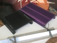
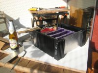
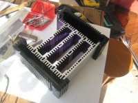
So I got a couple of big-ish heatsinks from one of the car audio repair places and bought a couple of pieces of alum. to help fit things together. (First photo below shows heatsinks before doing anything.) Then spent a couple of sweaty hours with a hacksaw in midday Brasilia heat, producing what you see in the second and third photos. Bottle of liquid refreshment gives scale. (My wife: "If you always complain of how tired you are after doing this stuff why keep such a stupid hobby?..." Me: "Almost all men's hobbies are like this....". Except fishing, I suppose.... Anyone here fish? Thought not....) I haven't bolted it all together yet - that's for some time in the week.
Here's the plan. None of these pieces individually is enough to heatsink an F4, but using 12 mosfets (or possibly only eight) I can spread their positiioning around all this metal, which is a good start with heat distribution. Leaving the bottom open, and only some sort of mesh on top to stop children's fingers getting in, there is loads of surface area to carry heat away. A best guess is about 6000-7000 sq. cm. My F5 has a little more than 7000 sq cm., although not ideally distributed, so we should be in the ballpark. If I can get my hands on a screw-down power resistor I'll try measuring the dissipation of the whole shebang. If it isn't enough for a full F4 maybe I'll try an 8-mosfet version. Assuming heat is a linear
function of the number of mosfets there should be enough heatsinking here for eight. If not I'll save it and use it for some other project.
Anyway, I'd be most glad to hear opinions on all of this, especially the effect of reducing the number of mosfet pairs....
Cheers
Nigel
OK, I'd still like to hear what people think about my last question, but I've decided to go ahead and see what will happen. (diy, right??) I'm going to have a go at an F4, possibly only with 2 mosfet pairs on each side, but trying to do it as cheaply as possible (without seriously compromising the sound, or there's no point...)
So I got a couple of big-ish heatsinks from one of the car audio repair places and bought a couple of pieces of alum. to help fit things together. (First photo below shows heatsinks before doing anything.) Then spent a couple of sweaty hours with a hacksaw in midday Brasilia heat, producing what you see in the second and third photos. Bottle of liquid refreshment gives scale. (My wife: "If you always complain of how tired you are after doing this stuff why keep such a stupid hobby?..." Me: "Almost all men's hobbies are like this....". Except fishing, I suppose.... Anyone here fish? Thought not....) I haven't bolted it all together yet - that's for some time in the week.
Here's the plan. None of these pieces individually is enough to heatsink an F4, but using 12 mosfets (or possibly only eight) I can spread their positiioning around all this metal, which is a good start with heat distribution. Leaving the bottom open, and only some sort of mesh on top to stop children's fingers getting in, there is loads of surface area to carry heat away. A best guess is about 6000-7000 sq. cm. My F5 has a little more than 7000 sq cm., although not ideally distributed, so we should be in the ballpark. If I can get my hands on a screw-down power resistor I'll try measuring the dissipation of the whole shebang. If it isn't enough for a full F4 maybe I'll try an 8-mosfet version. Assuming heat is a linear
function of the number of mosfets there should be enough heatsinking here for eight. If not I'll save it and use it for some other project.
Anyway, I'd be most glad to hear opinions on all of this, especially the effect of reducing the number of mosfet pairs....
Cheers
Nigel
Attachments
silly ZM here 
mentioned mini F4 ( with just one pair of outputs ) was meant as joke , but practical one - either mini follower for usual speakers or proper follower for 16 Ohms speakers as mine .
regarding headphone amp - it's pretty known "secret" that almost any amp can be scaled down to became dedicated HP amp , under condition that PSU voltage and Iq are still big enough to preserve linear operation and function of all active parts .
Papa , and few other DiyAs , sez many times that 15V per leg is pretty much lowest value you can use for stages using mosfets ;
that's pretty general condition , presuming that active parts aren't cascoded etc .
btw - looking at these htsnks you scavenged - are you sure that you have enough thermal contact between different pieces ?
important if you need them as such ( one big heatsink ) not so important if not .......
anyway - they look so cute !
Hi ZM,
I wondered if it wasn't really meant as a serious suggestion - nonetheless, a "mini follower", as you put it, is what I was imagining. Suppose, for instance it was intended to follow an 8W Le Monstre, or similar, into 8 Ohm speakers; would a version with *two* mosfet pairs (rather than the three in a full F4 or the single pair in he headphone amp be adequate? What sort of power output would it have? A stupid guess would be 2/3 of the 25W the F4 produces, or about 16W... This would be a pretty interesting size for me... What do you think?
I'm planning on trying a +/-20V PSU I madefor the Hiraga 20W Le CLasse A. If it's too wimpy I'll build something better, but it would be nice to reuse if possible.
As shown they aren't bolted together so the photo may be deceptive. Plan is to clean off the anodizing on touching surfaces, use a little silicon grease, and bolt them so that the surfaces touch under a little pressure. This would hold the four inner pieces together and spread heat well. Since each piece has two mosfets (and hence heat is being produced in a dispersed way) I'm sure this is enough. Heat will also be transferred to the big black sidepieces (which will also have two mosfets each, if I can get twelve running), via other bolts, and also by tow strips underneath which will help to hold the whole thing off the ground and let air enter below. It's not too easy to describe, but when I have it all fitted together 'll post more photos.
Cheers
Nigel
Zen Mod said:silly ZM here
mentioned mini F4 ( with just one pair of outputs ) was meant as joke , but practical one - either mini follower for usual speakers or proper follower for 16 Ohms speakers as mine .
regarding headphone amp - it's pretty known "secret" that almost any amp can be scaled down to became dedicated HP amp , under condition that PSU voltage and Iq are still big enough to preserve linear operation and function of all active parts .
I wondered if it wasn't really meant as a serious suggestion - nonetheless, a "mini follower", as you put it, is what I was imagining. Suppose, for instance it was intended to follow an 8W Le Monstre, or similar, into 8 Ohm speakers; would a version with *two* mosfet pairs (rather than the three in a full F4 or the single pair in he headphone amp be adequate? What sort of power output would it have? A stupid guess would be 2/3 of the 25W the F4 produces, or about 16W... This would be a pretty interesting size for me... What do you think?
Papa , and few other DiyAs , sez many times that 15V per leg is pretty much lowest value you can use for stages using mosfets ;
that's pretty general condition , presuming that active parts aren't cascoded etc .
I'm planning on trying a +/-20V PSU I madefor the Hiraga 20W Le CLasse A. If it's too wimpy I'll build something better, but it would be nice to reuse if possible.
btw - looking at these htsnks you scavenged - are you sure that you have enough thermal contact between different pieces ?
important if you need them as such ( one big heatsink ) not so important if not .......
anyway - they look so cute !
As shown they aren't bolted together so the photo may be deceptive. Plan is to clean off the anodizing on touching surfaces, use a little silicon grease, and bolt them so that the surfaces touch under a little pressure. This would hold the four inner pieces together and spread heat well. Since each piece has two mosfets (and hence heat is being produced in a dispersed way) I'm sure this is enough. Heat will also be transferred to the big black sidepieces (which will also have two mosfets each, if I can get twelve running), via other bolts, and also by tow strips underneath which will help to hold the whole thing off the ground and let air enter below. It's not too easy to describe, but when I have it all fitted together 'll post more photos.
Cheers
Nigel
Zen Mod said:good enough
go for +/-20V , and use 2 pairs , as you say ;
Papa use 3 pairs to make amp capable of delivering proper output current ;
Actually, the plan is to use three pairs if the heatsinks will take it, two if not...
Any idea what power output 2 pairs would give?
if your speakers aren't current hungry , you can make compromises ;
if they are , think about using original circuitry
How can you tell how current hungry speakers are? (A reference for me to read up would be great...)
Cheers
Nigel
Zen Mod said:which speakers you intend to use ?
I'll probably try it with my B&W CDM2s in the living room, but I expect to use it more with the FE127es I have in my office. (If I replace the B&Ws in the living room in the near future it'll probably be for some other diy design based on Fostex's of some sort. I'd love the Jordans but they're too much money for the time being.)
Does this mean "current hunger" is just an empirical thing? Or can it be deduced for t-S parameters or something?
Cheers
Nigel
current hungry - at least when we are speaking about "normal" home speakers -is more related to nice ( ie. flattest as possible , without heavy dips) speaker impedance .
anyway - if you think tat you're almost there with 8W Hiraga , then F4 will give you necessary boost - but only current wise .
amp power is nothing else than ratio of voltage and current at load ( speakers)
F4 is power follower - it will push exactly same voltage you threw it in , but it will feed more current through load if needed , than yur wimpy amp you use to drive it ( generally speaking , even if Hiraga 8W is certainly proper candidate to call it wimpy )
)
re-read few times F4 pdf . Papa already answered there on most of your questions
regarding amp power calc - just google , you'll find several tutorials , certainly better explanation than I can type right now .....
in any case - with +/-20V you'll have little less W at output , but don't loose sleep about that ....
anyway - if you think tat you're almost there with 8W Hiraga , then F4 will give you necessary boost - but only current wise .
amp power is nothing else than ratio of voltage and current at load ( speakers)
F4 is power follower - it will push exactly same voltage you threw it in , but it will feed more current through load if needed , than yur wimpy amp you use to drive it ( generally speaking , even if Hiraga 8W is certainly proper candidate to call it wimpy
) re-read few times F4 pdf . Papa already answered there on most of your questions
regarding amp power calc - just google , you'll find several tutorials , certainly better explanation than I can type right now .....
in any case - with +/-20V you'll have little less W at output , but don't loose sleep about that ....
I'm still doing the metalwork on heatsinks, and tomorrow I'll ttry to buy compenents.
Here's a question for someone with more experience than I have: I need to match mosfets for the outputs on the F4. I presume it's OK to match in threes; that is, the three N-fets on one channel need to be matched to each other, but not necessarily matched too closely channel-to -channel. So here's the question: experience says I will likely need how many IRFP240's to get two sets of three matched? I ask because unlike many people on the forum it'll be a long time before I use up a large number of extra mosfets, so I don't want to exaggerate on numbers... Does 8 sound overoptimistic?
Cheers
Nigel
Mosfet alternatives?
Hi all. I've just got back from my local electronics supplier, whom I like to support when possible. The output mosfets are going to be really pricy - the IRFP9240 is US$5 each, so buying a reasonable number for matching is probably not practical. I can try and buy online, which might help a bit, but importing brings its own problems of import taxes....
I should add, in light of my questions above, that I am hoping the heatsinks will take three pairs per channel, and will only reduce to two if necessary.
(I also checked the Fairchild equivalents - I can buy the FQA12P20 from Farnell online, but the N-channel equivalent is still extremely expensive - nearly US$6 each.)
There are a few places in the big F4 thread where people talk about alternative mosfets, so I was wondering if people had suggestions for more economical alternatives.... If I understand correctly, the Int. Rectifier codes start "IRF", for instance IRF9610, and the ones that start "IRFP", for instance IRFP9240 are higher power ones, or something. Are the lower power ones going to be adequate? They are only biased at 0.5A, after all...
So, any ideas? Anyone else had the same problem?
Cheers
Nigel
- Status
- This old topic is closed. If you want to reopen this topic, contact a moderator using the "Report Post" button.
- Home
- Amplifiers
- Pass Labs
- Some beginner questions about B3 preamp and F4 power amp