How to lower bias
Hi all. I have a working version of the F4 up, following the ideas mentioned above. I am using two pairs of mosfets per channel, in this case IRF630 and IRF9630, since they were very much cheaper to buy in sufficient numbers to match and I gathered from the big thread that other people used them successfully. I had three pairs per channel, but I'm afraid I let the magic smoke out of one of them... Not quite sure how...
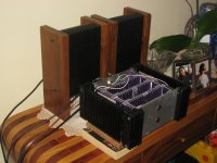
Just as well, perhaps, because with P1 at minimum I have about 400mV across the source resistors (.47R), which according to the manual is about twice what is suggested. I should add that I'm using a cap multiplier supply I have on hand, which gives about 20-21V unloaded, but which is sagging a fair bit under the strain of running this F4. It all works fine (and first impressions are that it sounds great!) but it's a bit too hot... Been on for about 40 mins, and the heatsinks near the mosfets are at 54 degrees. (ambient is about 27 this evening.)
So it seems to me that an adjustment of something is in order, to bring the bias down a little... so my question is how to do this. My naive idea is to put another resistor parallel to R9 (the 10K resistor connecting to P1) to lower the overall resistance between the two pins of the TL431, but I am unsure if I need to do something in the symmetrical position (by which I mean R8). Any ideas?
I'll post photos and other build-experiences when I can, and as always v. grateful for any help.
Cheers
Nigel
Hi all. I have a working version of the F4 up, following the ideas mentioned above. I am using two pairs of mosfets per channel, in this case IRF630 and IRF9630, since they were very much cheaper to buy in sufficient numbers to match and I gathered from the big thread that other people used them successfully. I had three pairs per channel, but I'm afraid I let the magic smoke out of one of them... Not quite sure how...
Just as well, perhaps, because with P1 at minimum I have about 400mV across the source resistors (.47R), which according to the manual is about twice what is suggested. I should add that I'm using a cap multiplier supply I have on hand, which gives about 20-21V unloaded, but which is sagging a fair bit under the strain of running this F4. It all works fine (and first impressions are that it sounds great!) but it's a bit too hot... Been on for about 40 mins, and the heatsinks near the mosfets are at 54 degrees. (ambient is about 27 this evening.)
So it seems to me that an adjustment of something is in order, to bring the bias down a little... so my question is how to do this. My naive idea is to put another resistor parallel to R9 (the 10K resistor connecting to P1) to lower the overall resistance between the two pins of the TL431, but I am unsure if I need to do something in the symmetrical position (by which I mean R8). Any ideas?
I'll post photos and other build-experiences when I can, and as always v. grateful for any help.
Cheers
Nigel
Re: How to lower bias
The fixed reference voltage of TL431 (about 2.5V) is between ref-pin and anode-pin (i.e. across (R9+P1)), I would slightly lower R8 to adjust the bias at lower zone.
")
njepitt said:
...
So it seems to me that an adjustment of something is in order, to bring the bias down a little... so my question is how to do this. My naive idea is to put another resistor parallel to R9 (the 10K resistor connecting to P1) to lower the overall resistance between the two pins of the TL431, but I am unsure if I need to do something in the symmetrical position (by which I mean R8). Any ideas?
The fixed reference voltage of TL431 (about 2.5V) is between ref-pin and anode-pin (i.e. across (R9+P1)), I would slightly lower R8 to adjust the bias at lower zone.
Re: Re: How to lower bias
Hi Babowana,
Do you mean in addition to lowering R9, or instead of?
Cheers
Nigel
Babowana said:
The fixed reference voltage of TL431 (about 2.5V) is between ref-pin and anode-pin (i.e. across (R9+P1)), I would slightly lower R8 to adjust the bias at lower zone.
Hi Babowana,
Do you mean in addition to lowering R9, or instead of?
Cheers
Nigel
Re: Re: Re: How to lower bias
Instead of . . . because lowering R9 inceases the bias.
Try R8 of 20K . . .
Still high? then, 18K . . .
njepitt said:
Do you mean in addition to lowering R9, or instead of?
And how much do you consider would be "slightly" lowering?
Instead of . . . because lowering R9 inceases the bias.
Try R8 of 20K . . .
Still high? then, 18K . . .
Re: Re: Re: Re: How to lower bias
OK, I'll try this... Actually I just tried lowering R9 to see what would happen... (this is diy, after all, right?) the answer is a fuse blew in the power supply
I'll let you know how things work out.
Thanks
Nigel
Babowana said:
Instead of . . . because lowering R9 inceases the bias.
Try R8 of 20K . . .
Still high? then, 18K . . .
OK, I'll try this... Actually I just tried lowering R9 to see what would happen... (this is diy, after all, right?) the answer is a fuse blew in the power supply
I'll let you know how things work out.
Thanks
Nigel
Well, it turns out I'm a bonehead... (but then, you all probably guessed that anyway, right?) RTFM, as they say... I was turning P1 the wrong way, since all the other amps I've done so far worked that way. Oddly enough I *did* check that "raising resistance raised bias", but obviouslky did it wrong. (I presume I checked different mosfets befre and after adjusting P1...) In any event, I got the bias down without more difficulty... I now have between 240 and about 270 mV on the various mosfets, and temp touching the heatsink very close to the hottest mosfet is 51 Celsius after an hour, which seems to be reasonable. I can probably get this down a bit farther with a few tweaks...
Thanks again
Nigel
Thanks again
Nigel
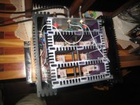
The next shows a little more of the internal workings. The idea was to put all twelve of the mosfets on little veroboard pieces together with source and gate resistors, and then to spread these around the chassis, for better heat management. I only have eight connected up now, as explained above, but same idea applies. When I have the inside ready I'll fix some sort of grille on top and bottom to makethings look nicer without affecting airflow (for cooling) too much.
Thanks again for all the help
Nigel
Thanks again for all the help
Nigel
Attachments
Closing the stable door...
For those of you who don't have English as a first language, there's a saying about closing the stable door after the horse has bolted - meaning taking precautions too late.
Yesterday I was listening to the F4 in the pictures above, when there was a pop in the left channel and an immediate drop in volume and sound quality. It turns out that one of the mosfets had failed (although I didn't realise this at once) creating a short, and about 15 VDC across the speaker..... Of cours,e being a dummy, I tried switching speakers to see if the problem was in the amp or in the speaker, and thus managed to blow the other speaker also....  (I've told this sob story on the full range forum, hoping for help in locating replacement drivers...) So I managed to switch out the mosfet and get the amp running, and I have reduced the bias current to about 0.43A instead of the 0.53 recommended, in the hopes of keeping temperatures a little lower and reducing the chance of this repeating, but this isn't an ideal solution, of course. Temporarily I am using speakers "borrowed" from an Aiwa mini system, which are far from ideal also (although rather better than I had expected).
So my question is what are people using for speaker protection? There are circuits on the ESP site which look quite good, but Rod Elliott suggests one of them isn't appropriate if input voltage is less than about 70V, which would rule out the F4. Any suggestions? I'm not worried about small DC offests, I just want to protect against this sort of catastrophic problem.
Cheers
Nigel
For those of you who don't have English as a first language, there's a saying about closing the stable door after the horse has bolted - meaning taking precautions too late.
Yesterday I was listening to the F4 in the pictures above, when there was a pop in the left channel and an immediate drop in volume and sound quality. It turns out that one of the mosfets had failed (although I didn't realise this at once) creating a short, and about 15 VDC across the speaker.....
Of cours,e being a dummy, I tried switching speakers to see if the problem was in the amp or in the speaker, and thus managed to blow the other speaker also.... (I've told this sob story on the full range forum, hoping for help in locating replacement drivers...) So I managed to switch out the mosfet and get the amp running, and I have reduced the bias current to about 0.43A instead of the 0.53 recommended, in the hopes of keeping temperatures a little lower and reducing the chance of this repeating, but this isn't an ideal solution, of course. Temporarily I am using speakers "borrowed" from an Aiwa mini system, which are far from ideal also (although rather better than I had expected). So my question is what are people using for speaker protection? There are circuits on the ESP site which look quite good, but Rod Elliott suggests one of them isn't appropriate if input voltage is less than about 70V, which would rule out the F4. Any suggestions? I'm not worried about small DC offests, I just want to protect against this sort of catastrophic problem.
Cheers
Nigel
So my question is what are people using for speaker protection? There are circuits on the ESP site which look quite good, but Rod Elliott suggests one of them isn't appropriate if input voltage is less than about 70V, which would rule out the F4. Any suggestions? I'm not worried about small DC offests, I just want to protect against this sort of catastrophic problem.
I build my own speakers -- so if something like this happens, I will just have to replace the woofers.
JJ
jupiterjune said:
I build my own speakers -- so if something like this happens, I will just have to replace the woofers.
JJ
Well, in this case I built my own too (they're a version of the monopoles from the diyaudio reference thread on the Full Range forum).... All joking aside I realise what you are suggesting is a sensible option in many cases, since the cost of the Fostex drivers isn't so high in the US. But they aren't available here in Brazil at any price, and importing is difficult et cetera.... The FE127e's I blew up were brought down from the US for me by a friend, so before risking a repeat experience I was thinking of looking into protection circuits.... (If I could just order a pair online at a normal price I'd likely just do it.)
Anyone have suggestions? (Please don't say I'm stuck with the Aiwa's...
Cheers
Nigel
- Status
- This old topic is closed. If you want to reopen this topic, contact a moderator using the "Report Post" button.
- Home
- Amplifiers
- Pass Labs
- Some beginner questions about B3 preamp and F4 power amp