.
Spring has come . . .
Leaves are too dry . . .
Light mountain fires . . .


.
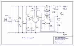
I will try a new voltage regulator for my F5 amp. Why . . . ?
- Wanna cut off few Vdc inbetween the 25Vac secondary and the 24Vdc rail I want.
- Wanna have a very stiff voltage source.
- Wanna have a current limiter--max. load current of 10A.
- Wanna have a short circuit current of 2A.
- Wanna remove the current limiter included in F5 amp circuit.
- Wanna try a thing the other diyers havn't tried yet.
- Will have a bleeder.
- Will have a soft starter.
- Most importantly wanna have another diy fun!
[/List=1]
I dun know whether I'm walking through the right direction towards a safe escape. I myself can't see a big picture of the forest, some parts of which are on fire.
>") <
<
Attachments
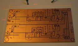
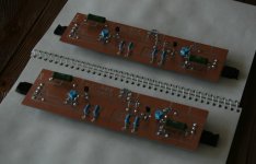
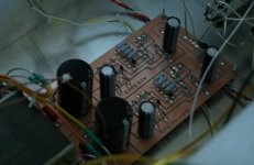
Have made very preliminary drawing on PC board, to check size and space of the the board required for components arrangement. It seems that the board could be reduced somewhat smaller . . . but . . . but . . . the chassis has plenty inner space . . . keeponrunning!
><
>
<Attachments
Babowana said:
I will try a new voltage regulator for my F5 amp. Why . . . ?
- Wanna cut off few Vdc inbetween the 25Vac secondary and the 24Vdc rail I want.
- Wanna have a very stiff voltage source.
- Wanna have a current limiter--max. load current of 10A.
- Wanna have a short circuit current of 2A.
- Wanna remove the current limiter included in F5 amp circuit.
- Wanna try a thing the other diyers havn't tried yet.
- Will have a bleeder.
- Will have a soft starter.
- Most importantly wanna have another diy fun!
[/List=1]
I dun know whether I'm walking through the right direction towards a safe escape. I myself can't see a big picture of the forest, some parts of which are on fire.
>
Rock on brother Babo!
I believe the 317/337 with pass transistor based regulator that I built really made
a positive difference in the sound character of the amp. I believe it gave more
definition throughout the sound spectrum. I believe this made for a more vivid
sound stage.
Maybe these things actually derive from being able to set the voltage on the
rails more accurately (to balance the pos and neg sides). Maybe they are due
to extra power supply filtering that I did at the same time. Maybe it is due to
better handling of power problems in my city. I don't know...
I will be interested in reading how your project progresses, and if you believe the
end product makes any audible difference. Good luck!
Robert
audiorob said:
...Good luck!
Thanks, Robert. I'm encouraged . . . moving one step forward.
>
<Attachments
Hi Babo
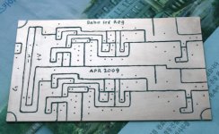
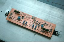
The way you used raw PCB to incorporate layout of traces using a "Dremel" type of drill gave me some interest to try it for some projects since I do not have etching pcb kit and all the chemical stuff required...
Regulating the F5 power supply should surely provide some interesting improvements...
keep us posted on the "before and after" sound comparison too.
fab said:
keep us posted on the "before and after" sound comparison too.
Hi,
Will try, but the progress is slow for certain reason . . . Be patient, pls . . .
>
<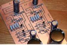
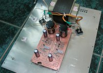
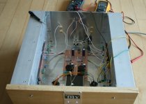
Babowana said:The populated board is ready to go into the chassis . . .
>
Hi,
Nice job
For the power mosfets will they be attached to the main amp heatsinks or use separate dedicated smaller heatsinks? If on the main heatsink, how will you attach the one in the middle of the pcb ?
Additionally, how do you control the depth of the drill in the pcb to remove the copper to do the layout? unless I have totally misunderstood your technique...
Thanks
fab said:
If on the main heatsink, how will you attach the one in the middle of the pcb ?
Additionally, how do you control the depth of the drill in the pcb to remove the copper to do the layout?
Yeah . . . I attach the mosfets on the main heatsinks and use lead wires to the PCB. The lead wires have been ok for me. If I consider that the wire length is too long, I solder the gate resistor (220R) directly to the gate pin, and then I send the lead wire to the PCB.
I control the depth of the drill, using my three-finger force (like pen holding). That's all.
>
<Attachments
Babowana said:
...
I control the depth of the drill, using my three-finger force (like pen holding). That's all.
>
You are an artist

Babowana said:Had a problem in the right channel of the new amp . . .
But, it successfully fixed . . .
and bias adjustment for the both channels finished . . .
>>
Nice job. Now stop teasing us and tell us how it sounds
...fab said:
Now stop teasing us and tell us how it sounds
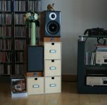
Give me a bit more time. I have just finished system set-up:
Babo voltage-feedback shunt reg. >> excellent B1 buffer >>
Babo voltage-feedback serires reg. >> great F5 power amp >>
four ATC SCM7 spakers
Two speakers (paralleled) per channel . . . total four . . .
Papa might laugh . . . I have chosen the bias for F5 at 0.85A

>
<Attachments
My second son (26) has never shown his interest in my diy audio. I have sometime wanted to borrow his ears for sound test, but in vain. He has always said: "I don't know about the sound quality. I just listen to my favorite music." He has been like that . . . 
We were on the lunch table yesterday. ???. . . He was quietly eating, and slowly opened his mouth: "It's quiet and the sound is very good!" Ehh . . . ? It was a surprising comment from him . . . I was making inner smile . . .
I believed he meant that S/N ratio was high and the sound was great. Yes, it was. Sure that it was supported by the power supply regulation.
Nigel Kennedy, KAFKA, II. I BELIEVE IN GOD
The big stage is filled in with energetic Drum and Bass . . . The large hall is filled in with Choir . . . There is rhythm guitar . . . And, electric and acoustic violins floating above them . . . Mmm . . . as if Jimi Hendrix were playing the violins . . .
I highly recommend you to join me, build and enjoy
><
We were on the lunch table yesterday. ???. . . He was quietly eating, and slowly opened his mouth: "It's quiet and the sound is very good!" Ehh . . . ? It was a surprising comment from him . . . I was making inner smile . . .
I believed he meant that S/N ratio was high and the sound was great. Yes, it was. Sure that it was supported by the power supply regulation.
Nigel Kennedy, KAFKA, II. I BELIEVE IN GOD
The big stage is filled in with energetic Drum and Bass . . . The large hall is filled in with Choir . . . There is rhythm guitar . . . And, electric and acoustic violins floating above them . . . Mmm . . . as if Jimi Hendrix were playing the violins . . .
I highly recommend you to join me, build and enjoy
>
<Attachments

HiBabowana said:My second son (26) has never shown his interest in my diy audio. I have sometime wanted to borrow his ears for sound test, but in vain. He has always said: "I don't know about the sound quality. I just listen to my favorite music." He has been like that . . .
We were on the lunch table yesterday. ???. . . He was quietly eating, and slowly opened his mouth: "It's quiet and the sound is very good!" Ehh . . . ? It was a surprising comment from him . . . I was making inner smile . . .
I believed he meant that S/N ratio was high and the sound was great. Yes, it was. Sure that it was supported by the power supply regulation.
Nigel Kennedy, KAFKA, II. I BELIEVE IN GOD
The big stage is filled in with energetic Drum and Bass . . . The large hall is filled in with Choir . . . There is rhythm guitar . . . And, electric and acoustic violins floating above them . . . Mmm . . . as if Jimi Hendrix were playing the violins . . .
I highly recommend you to join me, build and enjoy
>
Well ...It sounds inviting !.
Can you provide a comparison with the F5 w/o the voltage regulator...
Did you use the same capacitor bank value as the one suggested in Pass F5 documentation?
Babowana said:
Papa might laugh . . . I have chosen the bias for F5 at 0.85A
Why only 0.85A with such big heatsinks....

fab said:
Did you use the same capacitor bank value as the one suggested in Pass F5 documentation?
Why only 0.85A with such big heatsinks....
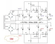
No. Look at my old PSU having total 198,000uF. I compared the sound new one with this old one. I prefer new one. And, for your info, I have never tried the one suggested in Papa's documentation.
Why only 0.85A? Ehh . . . it could increase distortion values. But, my ears do not sense the increased distortion . . .

>
<Attachments
- Status
- This old topic is closed. If you want to reopen this topic, contact a moderator using the "Report Post" button.
- Home
- Amplifiers
- Pass Labs
- Babo Tries New Voltage Regulator for F5