Right.Babowana said:
Giovanni, thanks for the reference. It gives me a clear picture.
I was wondering why R13 was there. It seems that now I understand the reason. It is to keep very low dc voltage at the output of the servo, and by doing so, to make the dc offset at the amp's output "drift vertually at 0V", isn't it?
Ciao,
><
Probably it could be removed, but in my experience op-amps likes it.
Thank to all of you for your help.
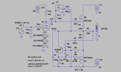
Following all your sucggestion I ended up with another version, THIS.
Improvements (really?):
1. No feedback on the input tube(s); the operating point has been choose in manner to grant a good linearity in the whole working region.
6N6P tube are already a really linear tube.
I can even add a few of cathode degeneration to make it more linear.
2. More juice to drive the output fet? Well, two tubes in parallel and double the current from the top CCS should help.
3. CCS to be defined: tube gurus suggested me to use a cascode CCS for better response, I have to decide yet which one (I have few cascode, high voltage CCS already built, must try few of them in this application).
4. P mosfet: choosen to "respect" the Aleph output topology and also because the IRF9530 fet has a much lower capacitance (ariund 800 pF).
Ciao,
Giovanni
revintage said:Hi again,
The lower device seems to be upside down. To make it work Source should be upwards and Drain to negative.
Wouldn´t it be more important to use the servo to keep output a 0V instead of using it for monitoring Iq?
Thank you very much.
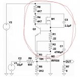
Eventually inverted the mosfet and corrected the voltage sensing on the output.
Here it is.
Ciao ciao
Looking better, but still 5 more parts than needed in the Aleph.
Ditch R3, R5, R9, R10, and C2. Direct couple the source of Q4
to the emitter of Q3.
Values for R14 and R16 might need to be reduced by half each.
As the emitter of Q3 now sees the voltage span across both.
R7 is of debatable necessity in the emitter coupled circuit,
as the source of Q2 is a voltage follower of the emitter. I'd
at least reduce the value of R7 a bit. Maybe 100R is enough.
kenpeter said:
Ditch R3, R5, R9, R10, and C2.
So, you want to change Aleph current source to CCS?
What is the main reason . . . ?
kenpeter said:
Values for R14 and R16 might need to be reduced by half each.
As the emitter of Q3 now sees the voltage span across both.
Why not just removing one of them instead of the two reduced. . . if necessary . . . ?
>
<Hey kenpeter,
Take a look at this paper:
http://www.passdiy.com/pdf/zen-ver2.pdf
Giovannis Aleph CCS is in fig 6.
Take a look at this paper:
http://www.passdiy.com/pdf/zen-ver2.pdf
Giovannis Aleph CCS is in fig 6.
Babowana said:So, you want to change Aleph current source to CCS?
What is the main reason . . . ?
Why not just removing one of them instead of the two reduced. . . if necessary . . . ?
>
Its not CCS. Its just like Aleph, only direct emitter coupled.
It needs two resistors with the load connected roughly in
the center. Exact center seems to work fine in your case.
Its two amplifiers in parallel with a fixed voltage drop
spanning them. Top amp is merely an offset follower
of the bottom amp, which retains any SE character.
Aleph holds the top amp 1 Emitter drop higher than the
lower amp. That drop across both resistors then sets
the quiescent current. And simply let the magic happen...
Tap your NFB from the same center tap as the load.
And from the load's perspective, the resistors vanish.
kenpeter said:
Its not CCS. Its just like Aleph...
I see . . . ah ha . . . you mean this . . .
It looks like a "push-pull" retaining SE character of the lower mosfet . . . Maybe I'm not right . . .
>
<Attachments
Last schematic.
I used for the first time LTspice, a wonderful program!
Really easy to understand and amazingly powerful.
THIS is what I ended with, following all of your suggestions.
Active current source from Kevinkr, no feedback, no ccs.
And the simulation is great!
I have no idea on how to test distorsion with LTspice: any help?
Ciao,
Giovanni
You are just trying to follow a voltage, don't make it so complex.
See Post#24
http://www.diyaudio.com/forums/showthread.php?s=&threadid=140114
See Post#24
http://www.diyaudio.com/forums/showthread.php?s=&threadid=140114
Here it is the LTspice file.
This power source permit me to xtend the output negative swing to its maximum; the simulation shows I can push the output up to almost 28Vpp before clipping of current distorsion... for an output power, on 4 ohm, of about 24Wrms!
Not bad, for 15+15 of supply.
I'd like to understand how to calculate THD and distorsion... please help me.
I really like what I've done, I'm sure it couls become a great amplifier.
I've also added a low pass filter at the intergarot ouput; this way the C1 is rightly loaded and its current is perfectly sinusoidal, lowering the driver output distorsion.
Complex? not so much. Actually is really simple, the only drawback is I had to add a separate, floating 15V power source (V2).You are just trying to follow a voltage, don't make it so complex.
This power source permit me to xtend the output negative swing to its maximum; the simulation shows I can push the output up to almost 28Vpp before clipping of current distorsion... for an output power, on 4 ohm, of about 24Wrms!
Not bad, for 15+15 of supply.
I'd like to understand how to calculate THD and distorsion... please help me.
I really like what I've done, I'm sure it couls become a great amplifier.
I've also added a low pass filter at the intergarot ouput; this way the C1 is rightly loaded and its current is perfectly sinusoidal, lowering the driver output distorsion.
Attachments
Rev,
While I do agree a bootstrap is the answer here:
Why would you introduce a bootstrap worth of error into the
primary source follower? And then copy that error into Aleph?
The errors are common mode, reinforce and do not cancel.
The impedance at the Aleph's source is much lower than a
simple follower, as it has local feedback from the transistor.
This would be the very best place to swing a bootstrap.
The error is much smaller, and only affects that one end.
Attachments
 , the connection to the emitter is consideredbetter with respect to noise reduction. Any comment? Tks . . .
Oops . . . Sorry, Kenpeter.
I have missed Revintage's buono_02.txt file in post #37.
Revintage has connected C2 to the emitter of Q2 and your
post#38 has been about that connection . . .
Ah, my poor . . .
. . .
Anyhow, don't you think that the C2 connection to the emitter of Q2 is considered better with respect to the noise reduction? Tks for your response.
><
I have missed Revintage's buono_02.txt file in post #37.
Revintage has connected C2 to the emitter of Q2 and your
post#38 has been about that connection . . .
Ah, my poor
. . .Anyhow, don't you think that the C2 connection to the emitter of Q2 is considered better with respect to the noise reduction? Tks for your response.
>
<- Status
- This old topic is closed. If you want to reopen this topic, contact a moderator using the "Report Post" button.
- Home
- Amplifiers
- Pass Labs
- Hybrid with Nelson topology