I found that the boost from -85dB to -105 dB happened only after the modification of adding additional feedback & X connections.
The X resistors are becoming very value sensitive with a +20 dB performance peak at a certain point, while with only one X connection the values seem to be not very important.
There are now high impedance feedback connections from the output stage to every arm of the differential input amps, and low impedance feedback connections to every leg of the differential input amps.
The X connections may be like in the schematic or also crossed between the legs.
However, I'm not sure what will happen in the real world.
An externally hosted image should be here but it was not working when we last tested it.
Now... is that an X ? 
An externally hosted image should be here but it was not working when we last tested it.
Here is a simplier X-Circlotron :
http://www.diyaudio.com/forums/showthread.php?postid=923481#post923481
Built multiple versions with Toshiba & IRF MOSFETs. Sounds great.
(My usual bias !!)
Patrick
http://www.diyaudio.com/forums/showthread.php?postid=923481#post923481
Built multiple versions with Toshiba & IRF MOSFETs. Sounds great.
(My usual bias !!)
Patrick
Nelson Pass said:I don't know - it doesn't fit on my screen, and anyway
its got more than three parts in it.
Master, I hear your voice.
My circuit is to complicated.*
Just removed the VAS.
*less is more
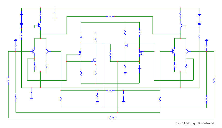
Each side has its own differential input amplifier (da).
The outer da inputs serve for the input signal and also get feedback from the other side.
They are connected trough the impedances of the signal source and the input resistors which form some kind of R_magic.
The inner da inputs get feedback from the same side and are also connected to each other with some kind of R_magic.
There is also feedback from the same side to ( the connection of all three transistors of ) the da on each side and again there is a R_magic connecting the da's.
Each R_magic is small compared to R_feedback, so each of the feedback nodes receives signal parts from both sides.
Because the output signals ( = feedback signals ) are out of phase, the primary part of the signal from the dominating side is strongly attenuated by R_magic, but the error part - that is different between signals fom each side - is not.
I did a simulation with different 1V error spike sources on each output and the result is that each side reduces it's own error to 0,5V and reamplifies the error of the other side to 0,5V.
Both errors appear on both sides with 50% of original amplitude and are in phase and cancel each other on the load.
schematic updated
I found that the low impedance feedback connections are unnecessary, but the x resistor remains.
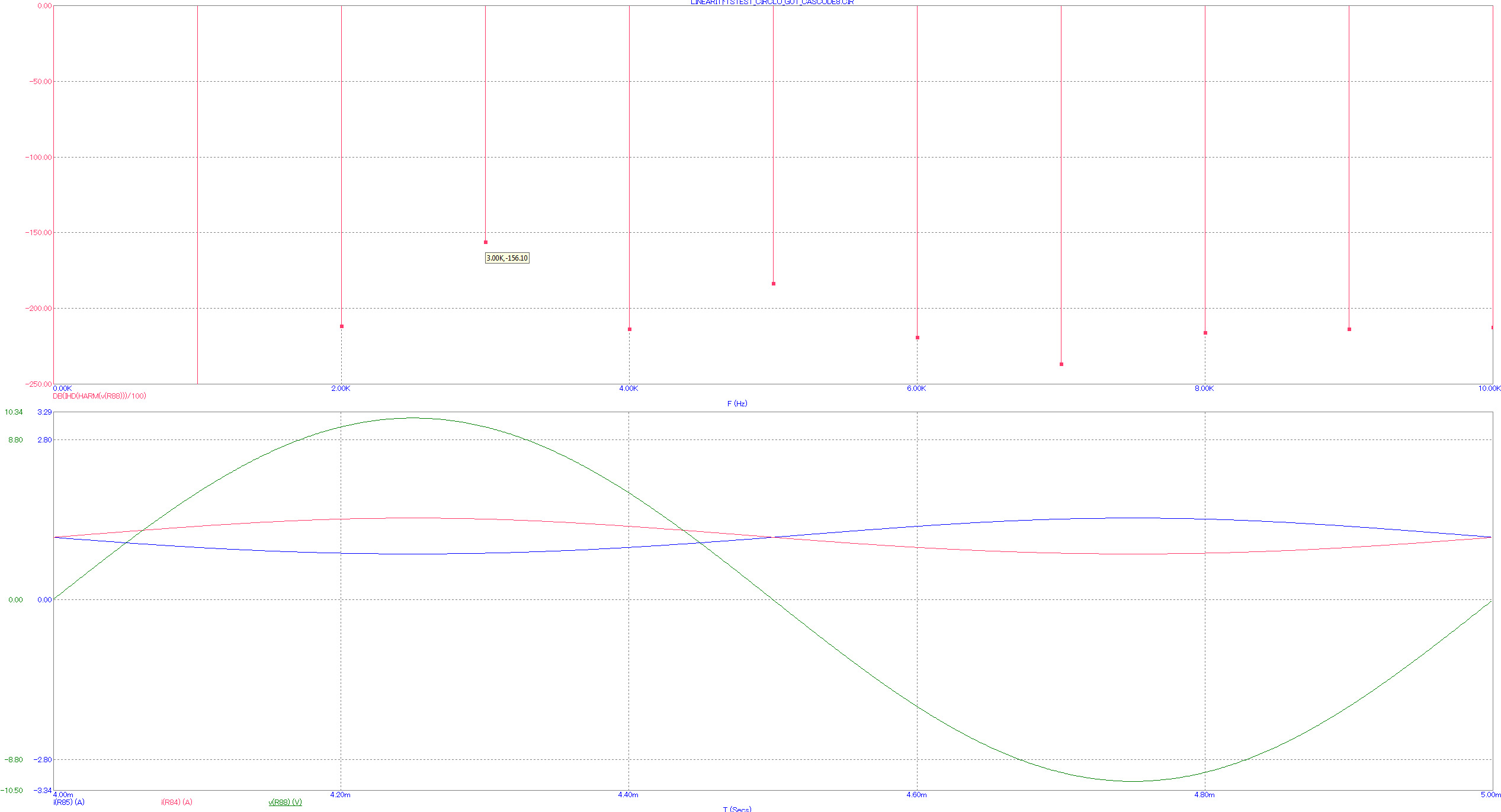
The circuit now optimized for +/- 10 V swing performs as follows in sim:
harmonics down to
+/- 2V swing -140 dB
+/- 10V swing -125 dB
+/-20V swing -86 dB
optimized for +/- 20 V swing:
+/- 2V swing -126 dB
+/- 10V swing -100 dB
+/-20V swing -98 dB
I found that the low impedance feedback connections are unnecessary, but the x resistor remains.
The circuit now optimized for +/- 10 V swing performs as follows in sim:
harmonics down to
+/- 2V swing -140 dB
+/- 10V swing -125 dB
+/-20V swing -86 dB
optimized for +/- 20 V swing:
+/- 2V swing -126 dB
+/- 10V swing -100 dB
+/-20V swing -98 dB
I never tried to built that thing and now after long time start to work again on the schematic.
At the moment in simulation it shows major improvements.
It can also work with no ground but has common mode output offset some hundred mV. 1 giga ohm proforma.
Looks any good ?
With output of 1V, k3 even more down...
At the moment in simulation it shows major improvements.
It can also work with no ground but has common mode output offset some hundred mV. 1 giga ohm proforma.
Looks any good ?
With output of 1V, k3 even more down...
- Status
- This old topic is closed. If you want to reopen this topic, contact a moderator using the "Report Post" button.
- Home
- Amplifiers
- Pass Labs
- Does that qualify as "X" ?