Maybe this is old hat to you, I don't know how much Aleph may
have evolved since the version of Nelson's Patent 5,710,522???
Anyways, we from the other side of the Sand/Glass curtain have
been abusing a current source we call "Anti-Triode" to the same
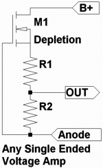
effect. Usually with a depletion Mosfet, and just two resistors.
A very simple totem topology as proposed by Michael J Kostner.
I like some things about both designs: Aleph and Anti-Triode
Simplicity: Advantage Anti-Triode
Direct Coupling: Advantage Anti-Triode
Enhancement Mode: Advantage Aleph
Consistancy of VGSon: Advantage Aleph
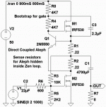
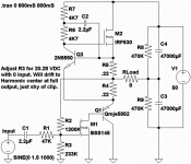
So, screwing around, I sorta blended the two...
Maybe I've ruined it, I don't know. You tell me.
Attachments
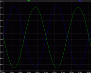
And here's the LTSpice.
Using only default parts and symbols.
--------------------------------------------
I had originally hoped for a 47K input
impedance, but had to settle for 600.
IRF530 gate capacitance, go figure...
I need to show you guys yet another
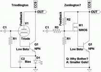
hybrid tube trick, The Triodlington.
where a bipolar transistor inherits
the Mu of a Vacuum Triode. Would
apply equally well to Zen, and allow
for a much smaller mosfet gate.
Another day perhaps.
Attachments
This is the Anti-Triode. Its strength is simplicity.
There is also no coupling cap (C1 in Aleph patent),
aside from inherent gate capacitance...
A lack of choices in depletion mode Fettery seems
to be its main weakness. We typically abuse the
Supertex DN2540. But VGS-On varies from batch
to batch. Neither of which is a concern for Aleph,
with its bipolar junction for reference.
------------------------------------
Aleph, Anti-Triode, Paraphase, SEPP, & H-bridge.
All trying to achieve basically the same exact
thing, with varying degrees of technical success.
Long term currents should be equal and in Phase.
Short term currents should be equal and out of Phase.
Here we simply hold the voltage across the two
resistors constant, and let the magic happen.
Without losing any advantages it holds now,
Aleph could learn this same trick, and ditch C1.
Thats all I'm saying.
Attachments
And here's the other thing I was talking about.
Get around for that huge gate capacitance.
Simply magnify a much smaller MOSFET.
To understand: First you have to know that a
Triode already has built in Zen. We call it "Mu."
The space charge between grid and plate is
an invisible distributed control surface, and
takes the place of R2/R3 in this schematic.
In either case, we give the bipolar's collector
an awareness of its standing voltage. It then
inherits the property of Zen or Mu, becoming
an amplifier of voltage, rather than current.
Its an odd bird, as it doesn't need resistance
below the emitter to be stable. The stability
comes from watching the collector. Go figure.
You could probably achieve similar results by
wrapping Zen around an IGBT. But so few
characterize for linear/audio, its hard to tell
from spec sheet how it might behave.
Attachments
Nelson Pass said:You realize, of course, that both these go waaay back.

Yeah, Like O.H.Schade wayback... If we are talking the
transform that turns a square law device into a Triode?
Without cheatin by strapping the screen to the plate.
1939 or something? I'd have to go digging to confirm.
Though he used transformer taps, rather than resistors.
The Pentode was a depletion mode device, and probably
no easy way to simultaneously direct couple and bias.
Still, he showed us the way.
Never fully understood Triodes or Zen till I read Schade.
Then it hits you: Its all the same thing, only different.
I'm not sure how far back an Anti-current source goes?
Probably some anchient variant of Paraphase. It keeps
getting re-invented and lost, over and over...
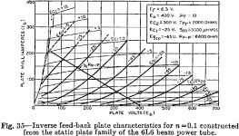
The graph is from "Beam Power Tubes" and shows how
an anode follower network transforms a Pentode into
a Triode. Very similar as Zen today does for a MOSFET.
Attachments
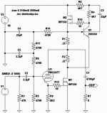
Here we see ZeSizzler, configured as a Sziklai Pair.
Zen (or Mu) equally aware of VCE either way, and
thus, no need for emitter current awareness.
I tried several sim runs with different NPNs as a
Darlington. But every time, that pairing seemed
to kill Zen's 2nd harmonic. I've never seen it do
that with a real Triode tube. I'm not sure why
the mosfet is more sensitive?
If you like 2nd harmonic sterility, the Darlington
may bear some further investigation. Though
It does nothing to reduce the 3rd and higher.
But Zen was always about SE, and this Szikilai
pairing seemed to keep original spectra intact.
Do note: Because it is a SE amp that distorts
as such, ideal DC center isn't exactly at 25V.
Nor is it the same at quiescent, as full output.
----------------------------------------
Because I'm never certain the exact value of
VG-Bias for any given mosfet. I might need to
allow for R3 to be grossly wrong, and abuse
a servo'd CCS to pull this node up or down.
Probaby up, there's more working volts to
play with on that side.... More on this later.
----------------------------------------
Also tried the Szikilai pairing for Aleph. Works,
but no better or different than one big Mosfet.
Same/Same. I put it back the way it was.
Also tried JFET follower to buffer the gate of
Zen's MOSFET and fake input impedance up.
Works, but adds a resistor more parts, and
wants another quiet rail at maybe 12V...
ZeSizzler was much simpler, for the same
upgrade in input impedance and gain BW...
You can play with the sim, and decide for
yourselves. I'll post the .ASC momentarily.
Attachments
Also threw in the model I used for the PNP.
You might have to hack it into "standard.bjt"
Its an easy cut-n-paste, once you find it.
Unless you've already built biploar lookalike
symbols that let you pick your own includes,
LT-Spice will force you to pick from Standard
list.
If there's a better workaround, I'm all ears.
You might have to hack it into "standard.bjt"
Its an easy cut-n-paste, once you find it.
Unless you've already built biploar lookalike
symbols that let you pick your own includes,
LT-Spice will force you to pick from Standard
list.
If there's a better workaround, I'm all ears.
Attachments
Something weird here. Not weird bad, just weird...
I believe it didn't matter Darlington or Sziklai, it was just
the relative strength of the transistor compared to the
zen mosfet that mattered. I forgot the curves of bipolars
bunch together with increasing current, as the mosfet's
spread further apart.
I didn't notice till I started throwing triangle waves at it.
My triangles had been distorted upside down of normal!
Not referring to inverted, just bent the wrong direction.
As its still wrapped in Zen (direct coupled local feedback
referenced to output voltage), it still has Mu and some
other Triodelike qualities. But its a whole different animal.
Possibly an anti-triode emulator? Which may then make
Aleph become the actual Triode emulator. Or whatever...
In any case, its not what I intended. Though it would
probably still sound similar. There's no denying the FFT
looks just like the normal Zen.
-------------------------------------------------------
These FETs seem rather weak when choices are pared
down to those with arbitrarily ultra-low gate capacitance,
comparable with real Triodes. Ended up using way more
bipolar HFE to make up the loss in Gm. Thats probably
where all my elaborate plans got thrown the curveball.
Back to the drawing board.
Nelson Pass said:You realize, of course, that both these go waaay back.

Still digging for those old references. Maybe
all this has taken place while I was asleep?
I do seem to sleep more than I'm awake.
I see you have the similar bootstrap in ZV9.pdf
But still no direct coupling between amplifier and
Aleph, using C9 220uF to achieve that coupling.
At what point did Aleph update to direct coupling
that I might have missed the transition? Or still
using the original RC coupling?
The Alephs are no longer made, except for a few remaining F3's.
The ones that were have a separate DC and AC input so that you can
easily set an arbitrary value for the DC current source (constant value)
vs the percentage of contribution to the AC output current.
The alternatives work fine also, but keep in mind that the power
resistor divider version will not typically be optimal with equal values
due to the limited transconductance of the device you use for the
current source.
From LTSpice of schematic shown in Post#1.
These are the currents in the two resistors.
Aleph, with its bipolar reference, has more
than plenty of Amps/Volt (gM) gain to work
with even the direct coupled two resistor
divider. Where both resistors are equal.
What you say is true enough for case of
an unassisted depletion mosfet. The top
resistor must be smaller to balance.
Attachments
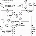
StOOpid ways to Abuse Mu. The other Zen.
Here, triode becomes the feedback network.
Yeah, for those who think of a triode only as
an obsolete JFET, I know this stage must look
like a slightly less than unity gain follower.
But its more than that! Plate is an input too.
A real triode is always in the triode region.
The "4th circuit" as OldEurope calls it.
Plate in, Cathode out...
-----------------------------------------------
This sims sweet. 3rd and 5th harmonics are
quiet, way down below the 2nd and 4th!
But I screwed up thinking how I might try
to stabilize DC bias with a low pass...
But too much phase shift round this loop.
Without 47K loading down the input, this
sort of servo almost wants to motorboat.
I'm still not entirely comfortable with it.
Shoulda just left the grid bias at some
fixed DC value, and tweak R9 to center
up the output wherever VGS works best.
No diff than regular Zen in this regard.
-----------------------------------------------
Certainly solves prob of low input Z.
But it aggrivates the prob of not being
able to pull the output below VGS...
With normal Zen, you got some DC
stored on the input cap that might
ride you through an output that dips
briefly below VGS.
But there is no storage here. Once
the plate drops to equal the cathode,
it shuts off. Just like any other diode.
Triodes aren't typically abused with
so little voltage on the plate, but they
still follow the same rule of Mu, and
thats all Zen needs for this circuit.
Attachments
Here, I think I've debugged most of the problems in the previous
version. Almost entirely caused by low plate voltage. Making G1
leak far too much, even before it gets forward biased. More than
2nd harmonic the reason DC center wanders all over the place...
Thanks to Duncan's model, or I'd never have spotted it.
A low value of grid leak resistor helps, but only higher plate V
stops the problem sufficiently. I thought about different ways
to bootstrap that feedback without ruining the direct coupled
nature of Zen and/or Mu.
I folded Zen back toward the upper rail, and tapped into 50%
ultralinear style. The triode is no longer operated near cutoff.
Now most of the soft clipping you see is the MOSFET and Zen.
Lower Mu and higher Gm triode was also a biasing necessity.
The MOSFET borrows the Triode's G1 for higher input impedance,
and borrows the Triode's Plate almost as-if a Pentode's Screen.
The feedback is not entirely Zen or Mu, but something between.
We can now swing the output within a gnat's eyelash of either
rail without any difficulty. Linearity is up, what little distortion
may remain is still dominated by triode-like even orders.
If I had the servo all figured out, it'd be worthy of a build.
The voltage at C2 can be tweaked anywhere from 25 to
50VDC. High enough not to make the triode grid too leaky,
reflected in about 1V adjustability for VGS bias as seen at
the cathode on the bottom end. R8 is where I would most
likely target for making that adjustment.
But I am about to go off on another tangent entirely....
Nelson may just flip his wig what I'm about to post next.
Current mirrors, folded cascodes, Alephs that appear out
of thin air, etc... etc... All his favorite stuff, only different.
Attachments
Why would anyone in their right mind do this???
Who said I was in my right mind? Or left for that mater.
All that matters (for both minds): Direct currents are
forced to be equal and in phase. Alternating currents
forced to be equal and out of phase... Nuff said.
More on this later.
Who said I was in my right mind? Or left for that mater.
All that matters (for both minds): Direct currents are
forced to be equal and in phase. Alternating currents
forced to be equal and out of phase... Nuff said.
Attachments
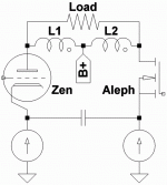
From Zen-V7 we learn that Nelson is no stranger to
transformer coupling. But the bane of transformer
coupling (and loudspeakers) is DC imbalance.
I'll assume anyone reading this post has read or
written that document first.
And I'm going to throw Nelson a further curveball.
I'll only Zen one side (represented by the Triode).
Aleph here not merely represented by a MOSFET,
it literally IS a MOSFET. Nothing else. Pure magic.
Both gates can float with the same reference
voltage, or different... Our current mirrors will
automagically serve up the correct autobias.
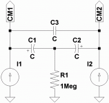
If this were a balanced circuit, the bridge cap
would have a very hard time. Source impedance
for a plain Jane MOSFET is extremely low. And
for Aleph here, it is.
By the very same trickery that gives Zen a low
drain impedance, it may also aquire a higher
than usual source impedance. High enough for
reasonable caps to bridge.
Again, I said this was not a balanced circuit.
Even if identical MOSFETS are used for Zen and
Aleph, they don't behave the same in context.
What you got here is a Folded Cascode. Aleph
holds the bridge voltage at some virtual AC
ground. Zen (with the higher source impedance)
dictates the (equal and opposite) AC current
for both halves.
And of course drain voltages are equal and
opposite, because they are transformer coupled.
Both devices deliver equal power into the load.
Now, whats funny to me. You can drive Zen's
gate and ground Aleph. You can drive Aleph's
gate and ground Zen. Or both in differential.
Its all the same, single ended Zenness....
Though I will say: that Aleph in this context
(no feedback network) has the higher gate
impedance, may be the preferable target.
"Wag the dog" I say.
On teh other side of the curtain, we call this
topology "Brute bridged Anti-Triode". Yesss.
I'll workup a full circuit for you in a day or two.
Got to get some real work done meanwhile.
Attachments
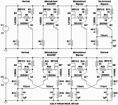
We see Aleph does an excellent job already
at matching mismatched MOSFETS. We see in
the first two examples: Nearly half a volt
difference in VGS between IRF510 and IRF530.
5.972V for the gate of M1, 5.433V for M2.
But Aleph holds the currents to within 5mA.
Aleph also does a pretty decent job with
deliberately mismatched bipolars... But
75mA is still a pretty significant error.
Compared with how well it had just dealt
with a really bad VGS situation.
Threw the pointless cap at M4 for laughs.
Nothing proved here. Except the loss of
.7V headroom in all circuits to follow.
Now we double the local feedback and
subtract half from afar... This is
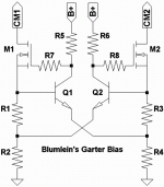
Alan Dower Blumlein's "Garter Bias."
For the mismatching MOSFET, we see an
improvement from 5mA to 2mA matching.
Aleph was already doing most of the
hard work. Probably not worth .7V bias
cost if that was all it was good for.
For the mismatching Bipolars, we see
an improvement from 75mA to just 24mA.
Now thats pretty significant! A factor
of three improvent in match.
Don't think anyone would choose to use
such deliberately mismatched components.
Only trying to show the concept works.
We are gonna explore some transformer
coupling next. And for that application,
matching DC might be significant.
Say for example: Abusing a dual voice
coil subwoofer as an autotransformer
for a full range loudspeaker...
Attachments
- Status
- This old topic is closed. If you want to reopen this topic, contact a moderator using the "Report Post" button.
- Home
- Amplifiers
- Pass Labs
- Possible improvements for Aleph?
