I thought the point was merely to keep you entertained?
I was actually about to make a point regarding the mirrors.
But I'm afraid my mind has gone and wandered off again in
another direction. Something cool enough it might just be
worth the temporary distraction. We'll get back to it soon.
Born of several nutty ideas tossed about this tube thread:
http://www.diyaudio.com/forums/showthread.php?s=&threadid=140699
Aleph with DC servo!
At DC, its a voltage source.
At subsonic, its a Gyrator
of increasing inductance.
Above 20Hz, its an Aleph.
Go figure...
Attachments
kenpeter said:Allrighty then, a Challenge!
Does your magic bag of tricks contain this one?
Yes it does.

Outside the context of abusing 200mV offset chip amps?
I can't find the link now. Not 100% certain that was you.
Maybe just something you had commented on. I don't recall.
Been driving myself crazy trying to follow long ago moved
or otherwise not functioning Pass links posted in forums.
I'm largely having to re-invent the old wheels over again.
Whatever, its entertaining...
Cause I can't predict the VGS-ON of any specified MOSFET.
Much less that any random pair are going to match well.
VBE-ON of Transistor (or Aleph) is much more repeatable.
My design above is already obsolete. I'll soon show you
exactly what I have changed, and more importantly: why.
But I got 150 Class-D amps and a few trays of DSP eval
modules waiting on me to push em thru the test bench.
And thats assuming none of em decide to fight back.
I don't know if I'll get enough of a break at work today
to revisit the Aleph. But maybe sometime this week.
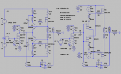
This drawing isn't clean as I wanted to show it.
But will have to do for now... Time is short.
The emitter coupled Aleph is a base follower,
not a source follower. And the voltage gap
between bases can be partially spanned by
other voltage drops besides Iq set resistors.
Schottkys here tighten the damping factor.
In the old drawing: currents into the gates
look like dErAnGeD squiggles, not sines...
The collectors were overshooting the mark,
and the local feedback was not helped by
bigger gate or base stoppers, nor extra
miller cap.
R3 and R10 are new. They put the bipolars
into a zenlike state without the miller cap's
phase shift. And the gate currents now look
like clean sines through the full audio range.
High order artifacts in the output FFT have
been quieted down considerably.
This added control also makes it possible to
smoothly shut off either gate without the
transistor overreacting. Before, they would
latch into deep saturation. Overdraining the
gates, making them harder to recharge later.
To show what I'm talking about:
I've deliberately biased this one into Class AB.
Sim this one, how smooth the crossover is!
Would have made a total mess before...
The portion of Zen voltage drop on the base
resistors also contributes to the 1.3V base to
base voltage gap. With some further tweaking,
the Schottky drops might not be necessary.
This is not optimized, I don't even know if the
MOSFETs specified in the sim are power types...
Attachments
Well, it seems after further study, that the Schottkys and
drop across the base resistors were 90% the magic bullet.
I don't think Schading down the collector voltage gain (Zen
style) had all that much effect...
The real deal was shimming the voltage gap, such that the
load had tighter interaction with both Aleph's inherent local
error corrections. The AB crossing then couldn't be anything
else but smooth.
I'm wondering if there was any cancellation of the Emitter's
nonlinearity in the corresponding drop across the Schottky?
They aren't exactly the same sort of diode, and I don't think
it would work if they were. Needs some resistance to set Iq.
I've been thinking again... Just smell the wood burning.
Anyways, been thinking about Aleph's emitter impedance.
Quickie empirical simmin to see what cuts the input volts
in half, shows the input Z varies 22K to 150K depending.
Like Ohio, high in the middle, round on both ends...
And half that if driving two emitters in compliment.
If you think of the bipolar as standing still, its the upper
device of a cascode. And the current is set by whatever
unspecified device might peer into the emitter's voltage.
Therefore, all current variations that charge or discharge
the gate must be driven by the input. This is why Emitter
input impedance droops at the high end. Its the Gate!
On the low end, it seems that bootstrap impedance
becomes somewhat leaky. But for middle frequencies,
Emitter input impedance seems to be quite high. This
variance could easily mess with whatever drives it.
Anyhow, a resistor or inductor to ground, of somewhat
less than naked emitter impedance sets everything right.
Also serves as ground ref for self servo...
-------------------------------
Okiedokie...
Lets say we use an inductor as our ground reference.
And transformer couple our signal in the same way...
We still need to level off those curvey emitter Z's....
Any a 600 - 4K7 resistor to ground would be the
obvious. But we don't really need a ground, the
inductor winding already has it well referenced!
So we tie the other end of our resistor directly into
the 8 ohm load. And scale it down such that it feels
and shares in perhaps 600 ohms worth of the real
load. The rest being driven by the Alephs.
You can see where this is going. More later...
--------------------------------
Anyways I got a tangent to explore first (act surprised).
Suppose I put a unity buffer between collector and
gate of the Aleph? And separately bootstrap the buffer
that does the actual gate driving. The input impedance
at the emitters should be HUGE.
Now supposing the buffer on the bottom is an inverting
type? The MOSFETS can now be identical. But this isn't
quite so simple as it sounds. The bootstap voltage swing
required is just as big as the top end's. But in exactly the
opposite phase and direction as the output.
What to do? What to do????
Wasn't quite what I had in mind or describing earlier.
But it gets the job done. LOOK MA! NO CAPS!!!
Seriously, there aren't any. Rail to rail too! Go figure...
Note both MOSFET channel polarities are now flipped.
If you made only one end this way, and the other Aleph
traditional, I suppose both output MOSFETS could then
be identical twins.
But I show you today a capless, bootstrapless version,
both ends... Probably needs a few stability parts thrown
at it, sprinkled around, ground in with a heel. R5 and R7
could also be merged into one resistor. This stripped
down, yet functional version, still gives the basic idea.
And of course, emitter impedance is now way up....
Though I've chosen to cut it down to 600 by sharing
a portion of the real load back to the driving circuit.
(as yet unspecified, pick your poison...)
Attachments
Nelson Pass said:That's very impressive, although it is no longer an Aleph. It is
starting to remind me of some of the error correction circuits of
Hawksford and Cordell.
Aleph? Maybe, maybe not, but its certainly Sigourney in a forklift.
kenpeter said:Aleph? Maybe, maybe not, but its certainly Sigourney in a forklift.
A most attractive metaphor.
Last circuit I posted doesn't appear entirely stable.
On the hairy edge of some crazy oscillations.
Can't put my finger on figure why? Its all DC coupled
round the loops, except for the gates themselves.....
I prolly gotta Schade back on some of the EC gains...
And look to make sure this follwer don't somehow go
over unity at any freq. Especially with input sharing
into the same load...
But even breaking that loop, its still unpredictable....
- Status
- This old topic is closed. If you want to reopen this topic, contact a moderator using the "Report Post" button.
- Home
- Amplifiers
- Pass Labs
- Possible improvements for Aleph?