This is an old article, but I am a little slow on the uptake and I am trying to understand what is going on. For reference, here is the article: http://www.passdiy.com/pdf/balzenpre.pdf
Can anyone explain R15 to me? How is it that it sets gain?
Second, would replacing R1 and R2 with current sources drive the gain super high, regardless of R15's existence?
Finally, any modern parts that would be preferable to the IRF610, or is it still a good choice?
Thanks
Can anyone explain R15 to me? How is it that it sets gain?
Second, would replacing R1 and R2 with current sources drive the gain super high, regardless of R15's existence?
Finally, any modern parts that would be preferable to the IRF610, or is it still a good choice?
Thanks
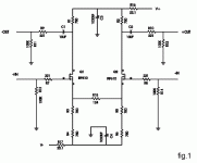
top left , page 3
anyway - Aleph P is still better than balzen
")
The gain of the circuit is the ratio of the impedances of the output circuit
divided by the impedances of the circuit that couples Q1 and Q2. The
summed impedance of the output circuit is essentially R1 plus R2, and
is 1500 ohms. The impedance of the coupling circuit is 124 ohms
summed with the approximately 12 ohm apparent source resistance of
each of the MOSFETs, or about 150 ohms. The gain of 10 (20 dB)
reflects the 1500 ohms divided by the 150 ohms. You can adjust the
gain of the circuit arbitrarily by adjusting the value of R15 without
affecting the quiescent DC values of the circuit. As you decrease the
value of R15 to 0 ohms, the gain will approach 50 (34 dB). As you
increase the value of R15, the gain decreases, with 430 ohms giving 10
dB of gain. Some of the performance curves presented later will reflect
both 10 and 20 dB gain settings.
anyway - Aleph P is still better than balzen
dsavitsk said:Yes, I saw that. It explains what the total gain is, but does not explain why, which is what I am after. It looks to me like some degerative feedback from one source to another, but I could use some additional explanation.
yup ...... sources are ( one to each other) sort of virtual ground
edit : it's always funny how Papa finds a way to explain things in simple way ;
I'm sometimes even thinking ( reading his papers ) how electronic is simple .......
naah .........

Attachments
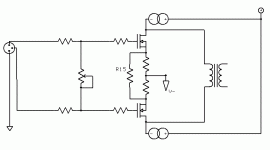
This is what I was thinking about. Basically, it seems like the load (whatever is reflected from the transformer) will replace the drain resistors from the BalZen in the gain calculation, and the gain will change depending upon both R15 and whether this is driving a high (10K - 50K) load, or something like a headphone load (32-300 ohms). Is this right, and will it work?
For a headphone amp, this can work to one's advantage with R15 = 32R, low Z phones will get unity gain and high Z (300R) phones will get a bunch of gain (about 10?). However, for a line stage into a 50K load, this could be an issue.
This begs a final question (two actually), too, which is what is the Zout of the circuit? With triodes, this would be a function of Rp and rp, but I have no idea with sand.
The other final question is what about a choke load for a mosfet? Again, with triodes, picking a choke is a function of rp, so I am stumped how to do it here. Maybe it won't work at all due to the mosfets being CCSes and more like pentodes themselves?
Attachments
dsavitsk said:This is what........
basically - neglect biasing and lower 750E resistors, and look at that as two plain triodes ;
with everything included - Ri , cathode degeneration etc. where degeneration resistor is R15
edit : I think that in your quiz example with xformer - reflected impedance is pretty trivial , just because these 3-legged critters have pretty low Ri , at least comparing with da toobz
- Status
- This old topic is closed. If you want to reopen this topic, contact a moderator using the "Report Post" button.
- Home
- Amplifiers
- Pass Labs
- Balanced Zen, R15, and Gain Questions