Very nice Bouke,Good evening gentlemen, The build is complete. We've been listening to the amps tonight and they sound just great. Here is a picture of the set now complemented with a pair of heavyweights. Note the Aleph Ono (the blue glow) on the right ready to go
Where are you listening to magneto-static speakers or electrostatic speakers.
Regards, Helmuth
Re: The Result
Great job. Congratulations....
Is that Audiostatic's?
")
Bakmeel said:Good evening gentlemen,
The build is complete. We've been listening to the amps tonight and they sound just great.
Here is a picture of the set now complemented with a pair of heavyweights. Note the Aleph Ono (the blue glow) on the right ready to go
Great job. Congratulations....
Is that Audiostatic's?
Morning!!
I wasn't able to get up this morning either... Let alone to leave my amps at home and come to work. I guess taking them with me on the bike wasn't an option...
Speakers ar Piega P5 LTD, and they are ribbons. At least, both high and mids are ribbon, low is cone-speakers in d'appolito bass reflex.
It's amazingly clear and powerful, and the bass is very tight. Playing Kodo (japanese drums) was a real pleasure heheh... I guess I have to re-listen all my music now...
Bakmeel said:LOL!!
That's all right Bees, I was calling goods inwards today to check if they had received anything yet... I't's clear now they haven't hahaha
No hard feelings... Do send your return address along. I have something here for you I want to mail back.
I don't know but it's probably cheaper to go and fetch those amps myself. 88Kg's excl, package material is a bit expensive to send with ups/tnt/dpd. ;-)
Not so Aleph
It's too bad gentlemen, the joy was short-lived...
Amplifier number 2, has failed. There was a pop, some hissing noise, after which I decided to switch off and unplug the speakers.
I've tried to measure out a bit to find the failure, but I haven't detected the source of the problem yet. I have excluded however the power supply and the main amplification stage. I suspect the problem is in the Front End PCB... probably one of the differential pair mosfets.
I have unmounted the Front End PCB, and I will take it to work tomorrow where I have better equipment to find and fix the bug. To be continued...
The good news is that my speakers are unharmed. I think I have been extraordinarily lucky that the failure didn't cause a large DC voltage on the output... ... My speakers are virtually unreplaceable to me and I almost would like to kick my own #ss because I did not test these amps more rigorously. Obviously, since this was the second in the build, I took less time to test everything and to allow a safe break-in period... Would have been safer that way.
Anyway, this thread isn't finished yet... stay tuned!
It's too bad gentlemen, the joy was short-lived...
Amplifier number 2, has failed.
There was a pop, some hissing noise, after which I decided to switch off and unplug the speakers.I've tried to measure out a bit to find the failure, but I haven't detected the source of the problem yet. I have excluded however the power supply and the main amplification stage. I suspect the problem is in the Front End PCB... probably one of the differential pair mosfets.
I have unmounted the Front End PCB, and I will take it to work tomorrow where I have better equipment to find and fix the bug. To be continued...
The good news is that my speakers are unharmed. I think I have been extraordinarily lucky that the failure didn't cause a large DC voltage on the output...
... My speakers are virtually unreplaceable to me and I almost would like to kick my own #ss because I did not test these amps more rigorously. Obviously, since this was the second in the build, I took less time to test everything and to allow a safe break-in period... Would have been safer that way.Anyway, this thread isn't finished yet... stay tuned!
Re: Not so Aleph
in that situation - consider using Quad's protection with triac ( thyristor ? ... memory ... ) as seen on some 405 models ;
if DC arrives , fuses pops ...... but DC will not reach precious spks .
Bakmeel said:.....
Anyway, this thread isn't finished yet... stay tuned!
in that situation - consider using Quad's protection with triac ( thyristor ? ... memory ... ) as seen on some 405 models ;
if DC arrives , fuses pops ...... but DC will not reach precious spks .
Frustrating
Well, I've been pounding on this failure for some time now, and I'm still not able to find the culprit. Here in the lab, I have hooked up the Front End PCB to a 1/6th scaled down output stage, and a 10 ohm resistor load. The supply is now +/- 20V
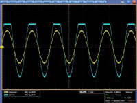
I have replaced all semiconductors except Q3 and the zener diodes, but the problem simply remains. I have attached a scope screenshot.
The yellow trace is the input signal, about 1v peak-peak.
The blue trace is the output, connected to a 10 ohms resistor.
As you can see, the output clips on the positive side, about where the input signal exceeds 600mV. If I reduce the input to below 600mV p-p, the amp stops clipping. If I remove the input, a small DC (about 200mV) remains on the output, but it is very noisy.
It appears something as if there something wrong in the differential stage. from the 15mA sourced by Q3, about 12mA passes through Q1-R14, leaving just 3mA for Q2. A clear unbalance. Also, Q1 Vgs is about 4.02V, and Q2 Vgs is 3.85. Apparantly just against saturation. Voltage across R14 is 4.21V, and it measures 392 Ohms as it should do.
Voltage across R16 is only 200mV, but 500mV across R15-R16.
Any suggestions?
Well, I've been pounding on this failure for some time now, and I'm still not able to find the culprit. Here in the lab, I have hooked up the Front End PCB to a 1/6th scaled down output stage, and a 10 ohm resistor load. The supply is now +/- 20V
I have replaced all semiconductors except Q3 and the zener diodes, but the problem simply remains. I have attached a scope screenshot.
The yellow trace is the input signal, about 1v peak-peak.
The blue trace is the output, connected to a 10 ohms resistor.
As you can see, the output clips on the positive side, about where the input signal exceeds 600mV. If I reduce the input to below 600mV p-p, the amp stops clipping. If I remove the input, a small DC (about 200mV) remains on the output, but it is very noisy.
It appears something as if there something wrong in the differential stage. from the 15mA sourced by Q3, about 12mA passes through Q1-R14, leaving just 3mA for Q2. A clear unbalance. Also, Q1 Vgs is about 4.02V, and Q2 Vgs is 3.85. Apparantly just against saturation. Voltage across R14 is 4.21V, and it measures 392 Ohms as it should do.
Voltage across R16 is only 200mV, but 500mV across R15-R16.
Any suggestions?
Attachments
LTP = Q1 - Q2 Differential pair? Yes. They are matched to <50mV. Not as good as the ones I had in first. They were <2mV
I've removed Z1 - Z4 --> no effect
I've replaced Z5 with a 10V type (didn't have another 9.1 at hand) --> no effect
I've replaced Q3 --> no effect.
I have unsoldered R7 / C8, values are OK, as far as I can check without unsoldering everything, all R's seem OK
I'm going mad here...
I've removed Z1 - Z4 --> no effect
I've replaced Z5 with a 10V type (didn't have another 9.1 at hand) --> no effect
I've replaced Q3 --> no effect.
I have unsoldered R7 / C8, values are OK, as far as I can check without unsoldering everything, all R's seem OK
I'm going mad here...Bakmeel said:LTP = Q1 - Q2 Differential pair? Yes. They are matched to <50mV. Not as good as the ones I had in first. They were <2mV
I've removed Z1 - Z4 --> no effect
I've replaced Z5 with a 10V type (didn't have another 9.1 at hand) --> no effect
I've replaced Q3 --> no effect.
I have unsoldered R7 / C8, values are OK, as far as I can check without unsoldering everything, all R's seem OK
first thing first ;
isolate just input stage ( LTP , diff. whatever you call it ) ;
try it and be sure that you have needed ...... and equal current through both mosfets .
only then you can try further ........ again soldering only important components ......
DC protection circuit
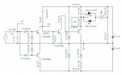
Congratulations...your Aleph 2 is beautiful. I made Aleph 4...and I'm also very satisfied. If you are interested I used some DC protection circuit in my design (I like my speakers and don't want blow them on first amplifier failure).
R1 is relay coil resistance (I used FINDER 40.61 24V/900R, one pole)
Here are all schemas: http://www.facebook.com/album.php?aid=158500&l=a5f40&id=1386409150
Attachments
Debug - step 1
Thanks Zen Mod and Majerovic for both you help and advice... I can use some expertise here...
So following Zen Mods thinking I'm now trying the systematic approach. This is step 1:
I have isolated the Current Source Q3 / Z5 and surrounding R's. Q3 - Drain is linked to GND. Supply is now 50V across the positive rail (V+) and Ground
- With a 10V zener and new IRFP9610 it sources approx. 25mA. Voltage across R11 = 5.4V, Voltage across Z5 = 9.5V.
- With the original selected zener, Isource = 23mA, V_R11 = 5.1, V_Z5 = 9.17V.
- With the original selected mosfet and zener, Isource = 22.7mA, V_R11 = 5.05, V_Z5 = 9.14V.
I checked C5 yesterday. It is fine, and polarity is ok.
Next, the diff pair.
- Status
- This old topic is closed. If you want to reopen this topic, contact a moderator using the "Report Post" button.
- Home
- Amplifiers
- Pass Labs
- Aleph 2 - The Final Build