
Hi
Is there a step by step procedure to set-up this F3 amplifier ? Also, test conditions please, ex no load or with load, input signal 500Hz or another frequency or simply short the input.
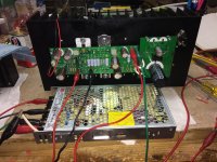
I’m using the CSAMPLE pcb (Thanks Chas) and matched Q1.
Power supply is a Meanwell 200W, one per channel + eventually the Mark’s SMPS filter.
Not sure what to set up first...
I haven’t touch R5 yet, so far I have the following by adjusting P1 and P2; 1V2, 3V, 8V and 21V.
Seems ok with the 8V and 21V, wondering about 1V2 and 3V. I need to get 1V1 and 3V5.
Thanks a lot.
Eric
Is there a step by step procedure to set-up this F3 amplifier ? Also, test conditions please, ex no load or with load, input signal 500Hz or another frequency or simply short the input.
I’m using the CSAMPLE pcb (Thanks Chas) and matched Q1.
Power supply is a Meanwell 200W, one per channel + eventually the Mark’s SMPS filter.
Not sure what to set up first...
I haven’t touch R5 yet, so far I have the following by adjusting P1 and P2; 1V2, 3V, 8V and 21V.
Seems ok with the 8V and 21V, wondering about 1V2 and 3V. I need to get 1V1 and 3V5.
Thanks a lot.
Eric
Attachments
I did many iterations of P1/P2 adjustment while the thing was playing music but I don't know that this is optimal. Based on some measurements made with shorted inputs and 8R dummy loads, I have a feeling that one will measure a higher and more proper Vds for the LU if one is doing adjustments under conditions of shorted inputs and 8R dummy loads.
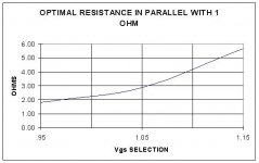
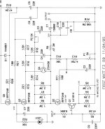
I first estimated the best value of R5 using a 5R pot in place of the fixed value and it led me to replacing the 2R, 2R, and 2R7 values for R3-R5 in the FW schematic with 2R7, 2R7, and 3R2, for a net source resistance of 1R04. As a consequence my amp has a bias of about 1.4A which is lower that the 1.65A spec of a true FW F3. Latest values for TP4 (LU drain) are 3.55V and 3.62V; TP3 (LU source) 1.35V and 1.41V; for Vds of ~2.2V, which is not optimal for lowest distortion (~2.5V is the goal based on Mighty ZM's testing).
You may or may not want to measure for oscillation on the output.
Thanks for your reply.
What made you decide to settle with a net source resistance of 1R04 (by changing R3-R5) ?
Is it based on listening tests OR because with your components you weren’t about to get a Vds of about 2.5 ?
I probably won’t be hitting the target so if I don’t it would be nice to know what matters the most and people’s deciding factor.
Thanks
Eric
Thanks for your reply.
What made you decide to settle with a net source resistance of 1R04 (by changing R3-R5) ?
Is it based on listening tests OR because with your components you weren’t about to get a Vds of about 2.5 ?
I probably won’t be hitting the target so if I don’t it would be nice to know what matters the most and people’s deciding factor.
Thanks
Eric
I couldn't get TP1 above 17-18V originally, when R3 and R4 were 2R and my 5R pot was cranked to it's maximum resistance. Jeff recommended to try increasing the values in this bank, so I first went to 2R7 for R3 and R4, with the power pot still in. I was then able to hit 20-21V with the power pot and the adjustment pots at reasonably intermediate values. When I pulled out the power pots to measure them, they were 3R5 on both channels, so I put in 3R2 resistors for R5. I can get 20-22V fine now. I think Bubba had a similar issue.
I've honestly been through so many iterations of this amp that I don't want to make claims about the sound, except for the most recent mod, but that's in the context of solving the oscillation issue I was having so let's not go there unless that becomes a concern for you.
Well now it’s a mess...I’ve replaced R5 with a 10ohm, 5W pot and I’m now able to get the required 3V5 but my 1V2 has gone up to 1V8..my 21V and 8V are also all over the place...
That’s it for tonight...
Tomorrow I’ll remove the pot and try to get what I had previously.
Hard to believe that there’s no calibration/tuning procedure.
Eric
That’s it for tonight...
Tomorrow I’ll remove the pot and try to get what I had previously.
Hard to believe that there’s no calibration/tuning procedure.
Eric
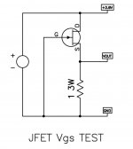
R5 is for setting 1V1 at LU source, which is first condition
then fine tune for 3V5 at LU drain, fiddling with P1, which is second condition
P2 is just for giggles, to fine tune Aleph CCS gain
then fine tune for 3V5 at LU drain, fiddling with P1, which is second condition
P2 is just for giggles, to fine tune Aleph CCS gain
Attachments
Thanks for your help.
I wish it was that simple...
Seems that the 1V1 is not just related to the value of R5, it also varies based on the position of P1 and P2.
I now have 1V1 but instead of 21V i used to have, now it’s 15V...
Not looking forward to repeat this with the second channel.
I wish it was that simple...
Seems that the 1V1 is not just related to the value of R5, it also varies based on the position of P1 and P2.
I now have 1V1 but instead of 21V i used to have, now it’s 15V...
Not looking forward to repeat this with the second channel.
You´re pretty brave using those crocodile clips for wiring things up.Not sure what to set up first...
My experience is, they fall off quicker than one likes and dang!
The ones I know and have somewhere also have really tiny cables with pretty high resistance.
To use those crocodile clips also for 120VAC input of the SMPS is simply not recommended.
(use some wire end ferrules or so and fix it with the screw terminal)
Be safe Eric and good luck with your amp!
FWIW this seems to be a somewhat general problem with this round of F3 builds, in that there's now at least three of us who were unable to hit 3V5 - 1V1 = 2V4 Vds values for the LU1014Ds. The symptom you describe, a dropping Aleph CCS voltage bias with increasing Q2 gate bias, and vice-versa, as well as increasing current through the circuit with higher LU1014D drain voltages, is something I observed as well. I made peace with a lower operating point, both in terms of current and voltage drop across the LUs. The amp does sound fine.Well now it’s a mess...I’ve replaced R5 with a 10ohm, 5W pot and I’m now able to get the required 3V5 but my 1V2 has gone up to 1V8..my 21V and 8V are also all over the place...
That’s it for tonight...
Tomorrow I’ll remove the pot and try to get what I had previously.
Hard to believe that there’s no calibration/tuning procedure.
Eric
This is speculative, but I'm using Vishay IRPF240s, not Harris or whatever else. It's possible the Rds(on) or gate capacitance or other important parameters of these somewhat generic MOSFETs might be interfering with optimal tuning of the circuit. Who knows what Papa used in the actual FW F3's.
I almost had all 4 voltage on target (pure luck) and then it went bad while trying to get it better.
You have to be extremely patient since there’s no procedure on how to properly calibrate this amp. It’s purely fiddling with P1 and P2 and hope for the best...future F3 builder good luck.
I’ll try tomorrow one more time and if I’m still annoyed by it it’s gonna go on a shelf for a while (years)
Thanks to people who tried helping.
May I make one last suggestion. Get it roughly right, put the lid on, and play it a while. Pair it with a passive preamp like a B1. Play it through speakers with minimal crossovers. Let it warm up an hour or more. Listen to it from the next room while eating dinner or playing on the computer. If it doesn't sound noticeably full, smooth, and warm, then I'm sorry, because it has all these qualities to me and that makes it a topology worth suffering for a little.I almost had all 4 voltage on target (pure luck) and then it went bad while trying to get it better.
You have to be extremely patient since there’s no procedure on how to properly calibrate this amp. It’s purely fiddling with P1 and P2 and hope for the best...future F3 builder good luck.
I’ll try tomorrow one more time and if I’m still annoyed by it it’s gonna go on a shelf for a while (years)
Thanks to people who tried helping.
Sounds good, thanks.
I’ll just take a break from it, I usually don’t struggle to get an amp to work properly but with the lack of a setup guide and tons of on-line contradictions on how to set it up properly it’s only normal.
I guess I’ve been spoiled with all my previous amps.
BR
Eric
I’ll just take a break from it, I usually don’t struggle to get an amp to work properly but with the lack of a setup guide and tons of on-line contradictions on how to set it up properly it’s only normal.
I guess I’ve been spoiled with all my previous amps.
BR
Eric
Well, I made some sort of progress.
I noticed that P2 would influence the DC setting which I found odd since P2 is wired in series with C3 which is AC coupled. Something was odd, probably some oscillation or something. I then decided to replace the SMPS (Meanwell 200W) by a linear supply, well, 10 minutes later everything was much easier to set-up and I then heard the F3 sing for the first time") . I do not intend to keep the linear supply since it's not powerful enough, instead I will use the 200 SMPS and add the SMPS filter from Mark.
. I do not intend to keep the linear supply since it's not powerful enough, instead I will use the 200 SMPS and add the SMPS filter from Mark.
When listening to the amp I had the following voltage; TP3;1V5, TP4;3V5, TP5;8V and TP1;21V which is close enough but the 1V5 which is adjustable via R5 was a little too high.
I then used a different volume pot (5 ohm,10W) in parallel to R5 and was able to bring the 1V5 down to 1V1. Cool, now I have my 1V1 but the 3V5 is gone completely and the highest I can go when fiddling with P1 is about 1V9...this amp is possessed... Q1 had a much better Vds before at 2V (3V5-1V5), now down to a sucky 0V7(1V9-1V1)...far from the 2V5 sweet spot.
After being on for about 1h, the maximum temp is 48C on Q2 and Q3. My bias is 1.55A, a few days ago it was 1.7A...another fun fact about inconsistency.
After supper I will power up the amp once again and I will most probably like in the past few times have totally different value for TP1, TP3, TP4 and TP5, no clue what's happening with this amp, I've never had such issues with an amp but I will continue to look for the issue.
Eric
I noticed that P2 would influence the DC setting which I found odd since P2 is wired in series with C3 which is AC coupled. Something was odd, probably some oscillation or something. I then decided to replace the SMPS (Meanwell 200W) by a linear supply, well, 10 minutes later everything was much easier to set-up and I then heard the F3 sing for the first time
. I do not intend to keep the linear supply since it's not powerful enough, instead I will use the 200 SMPS and add the SMPS filter from Mark.When listening to the amp I had the following voltage; TP3;1V5, TP4;3V5, TP5;8V and TP1;21V which is close enough but the 1V5 which is adjustable via R5 was a little too high.
I then used a different volume pot (5 ohm,10W) in parallel to R5 and was able to bring the 1V5 down to 1V1. Cool, now I have my 1V1 but the 3V5 is gone completely and the highest I can go when fiddling with P1 is about 1V9...this amp is possessed...
Q1 had a much better Vds before at 2V (3V5-1V5), now down to a sucky 0V7(1V9-1V1)...far from the 2V5 sweet spot.After being on for about 1h, the maximum temp is 48C on Q2 and Q3. My bias is 1.55A, a few days ago it was 1.7A...another fun fact about inconsistency.
After supper I will power up the amp once again and I will most probably like in the past few times have totally different value for TP1, TP3, TP4 and TP5, no clue what's happening with this amp, I've never had such issues with an amp but I will continue to look for the issue.
Eric
Well tonight I can say that 1 channel is done and is singing. Went back to my previous setup as TP3;1V5, TP4;3V5, TP5;8V and TP1;21V
To prevent funny business i soldered a 1nF on Q4 b,c thanks for the tip ZM. I also relocated the gate resistor of Q2 directly on Q2. Maybe the above 2 mods aren’t necessary but they can’t hurt.
My case isn’t built yet, it’s in progress. Once the amps are in the enclosure I’ll fine tune both channel once it has cooked for about 1h.
Lots left to do but now at least I know I’ll eventually have a working F3 !
Thanks to everyone who made this possible.
Eric
Sounds like you converged on the common recent operating point.Well tonight I can say that 1 channel is done and is singing. Went back to my previous setup as TP3;1V5, TP4;3V5, TP5;8V and TP1;21V
To prevent funny business i soldered a 1nF on Q4 b,c thanks for the tip ZM. I also relocated the gate resistor of Q2 directly on Q2. Maybe the above 2 mods aren’t necessary but they can’t hurt.
My case isn’t built yet, it’s in progress. Once the amps are in the enclosure I’ll fine tune both channel once it has cooked for about 1h.
Lots left to do but now at least I know I’ll eventually have a working F3 !
Thanks to everyone who made this possible.
Eric
May I make another suggestion?
About the 1nF mod- give it a listen on one channel only first for a while, with the other channel set up without. I've only done it on one channel and I'm pretty convinced it changes the sound on that side for the worse, even though it appeared to eliminate the persistent oscillation on that channel.. I haven't decided yet whether to rip it out or add one to the other channel, or attempt to play with the CCS value on that channel some.Hello all,
I was wondering if IRFP250's can be used in the csample F3 boards. I know there was a mention from NP in the original thread back in 2009, that it would be OK as a substitute for the IRFP240's. Just wanted to check before ordering.
Also it was mentioned that a BC546 could be used in place of the ZTX450 back in 2009. I have a few of the BC547B NPN that is from the same family with similar properties, so wondering if they can be a substitute.
Thanks for the help,
MM
- Home
- Amplifiers
- Pass Labs
- F3 Builders Thread