Hi Fred,
I'm not sure if you were aiming this at Jackinnj or me, but I'll take a stab at it.
I don't have anything but subjective opinion, but I have tried those CPF resistors, even on the Impasse, in 1 W, 2 W, and 3 W versions. I was hoping for a clean, metal flim sound, but they sounded hazy to me. They also ran really hot. If you wanted to try quads with cheaper but known good sounding resistors, you might try this;
CMF6015K000FHEK Vishay / Dale | Mouser
Not as compact as the SMD resistors, but a good, known audio resistor that is rated at 1 W as long as you keep it below 70 deg C. BTW, the board used for the quads is really a good heat sink, so they stay cooler.
Jac
Send me the part number from DK or Mouser etc and I will solder it up and compare. I can isolate out the power supply noise with a high voltage pile and DC filament supply.
Happy to. I can't measure something like this.
Here is the Susumu 1W SMD
HRG3216P-1502-B-T1 Susumu | Mouser
Alternatively, you could try the Dale CMF60 through hole that I linked in post #1182.
And of course the Panasonic ERG
ERG-3SJ153 Panasonic | Mouser
By the way, I don't claim to hear a feather drop. Not by a long shot.
Jac
Hi Jac,
My post was for Jack (in NJ), more like for a subjective measurement.
The resistor is metal film 25 PPM/C 1W.
I guess the smd resistor that you and David use is this which is thin film 25 PPM/C.
Both are somewhat similar in the PPM/C and wattage. The idea is to measure:
- each type in the 1W form
- each type in parallel/series form.
This way we can do a 4-way comparison.
The parallel/series construction can be somewhat tricky as it can add inductance. I think it is an interesting exercise.
I guess the smd resistor that you and David use is this which is thin film 25 PPM/C.
The parallel/series construction can be somewhat tricky as it can add inductance. I think it is an interesting exercise.
Yes, the resistor you linked is the one I used.
One advantage of using SMD or MELF resistor for this kind of quad construction is that you can keep the resistors close to the pcb and minimize inductance increase. I would guess that my homemade quads don't have much more than a Panasonic ERG (see post 1097).
One other interesting thing here is heat rejection. As an experiment, I soldered a 15k, 3W Dale CPF (tempco 100 PPM/C) to a proto board and ran it at about 1 W. I gave it 15 minutes to stabilize and measured temperature with an IR meter. I then repeated the experiment with the homemade 15k quad resistor. The results were that the Dale CPF temperature was 40 to 45 deg C above ambient and the quad was about 10 deg C above ambient. Of course, the CPF has much less surface area to transfer heat to the air. I was kind of surprised that a 3W resistor would be so close to it's 70 deg C derating temperature with only 1W.
Heat rejection is an important part of this because of power modulation distortion. The idea is that a hot resistor has a different resistance than nominal and that change in resistance changes the output of the circuit. That change of output is distortion. Since music has quiet and loud passages, the resistor will change resistance with the music and add non-linearity to the distortion.
Power modulation distortion is a function of the tempco and the temperature change as a function of power. Going back to the 3W Dale CPF and the Susumu quad, the CPF has higher tempco and higher temperature so it should have worse power modulation distortion. Relating back to the Panasonic ERG, it has much more surface area than the Dale CPF, so it would likely have a temp change with power in between the Susumu and the Dale but it also has a tempco of 300 PPM/C for the 3W and 350 PPM/C for the 1W. I don't know where a 1W Dale CPF would come out in a quad, but one of the advantages of SMD/MELF are that they are designed to transfer heat to the pcb, so its possible they may have a lower temperature even in a quad.
One last factor for the quad. Distortion in resistors is said to be mainly a function of voltage. In the quad, each resistor is operating a 1/4 the voltage of the total array. The theory says (per Groner) distortion of a quad should be 12 dB lower than a single identical resistor. I read an EE forum that suggests you can see this affect in Spice modeling, although I haven't tried it. That said, I'm not sure it will show up in measurements. X was working on the AKSA Lender pre and having trouble with a bit of 3rd harmonic distortion. On my suggestion, he tried a quad (without board) using thick film SMD resistors. The measurements did not improve.
Last edited:
if we are to believe that the FIRST WATT is the most important, 2.83V/10^5 =28.3uV noise.
Opps! I was looking at the data again and I goofed on the decimal place. The Panasonic ERG is 22 nV/Rt(f), not 220. Still a lot higher than good metal film resistors, but now a lot lower than the tube, for example.
I still stand by that they sound better, but the math isn't helping me anymore.
Jac
Opps! I was looking at the data again and I goofed on the decimal place. The Panasonic ERG is 22 nV/Rt(f), not 220. Still a lot higher than good metal film resistors, but now a lot lower than the tube, for example.
I still stand by that they sound better, but the math isn't helping me anymore.
Jac
Is that Figure 11 in the Seifert paper you are referring to?
Actually, I was comparing Figures 7 (Dale CMF55), 8 (Panasonic ERG), and 9 (Caddock, for curiosity). Those are 100R comparing a range of types and power rating.
Figure 11 is 10k resistors and it doesn't have the correct Panasonic. The Panasonic ERJ shown in Figure 11 is a thick film SMD rated at 1/4 watt. It does have the Dale CMF55 so you can compare the effect of resistance on current noise. All of the tests are at 10 volts across the resistor.
Almost too much information, isn't it.
Jac
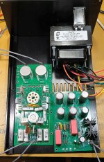
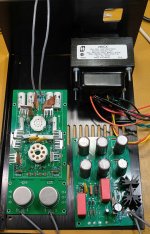
A question for the more experienced folks on this thread/build. Finally got a case in yesterday. On my other preamp builds I have gone with wide and deep cases, with good separation between power supply and preamp board and in and out connectors.
Here I am trying to keep a more modest size allowing for the height of the transformer.
So the questions I have are, will there be issues with the transformer and PS right beside the Impasse board, and/or if there isn't then would I be better facing the input transformers to the rear allowing for a close connection or flip the board so the outputs are closer?
Or does any of this really matter? Photos attached.
Tnx
David
Attachments
I don't qualify as one of the more experienced, but here is my two cents.
1. input signal a short run to the Impasse board. tightly twisted of course.
2. trafo at the opposite end of the case from the input
3. if you have to run the mains power and the input in the same panel, have the mains power cord run as far from the Impasse board as possible and at roughly the same level as the Impasse board. I have read that a source that is edge level to a pcb with have less interference than on at a big height difference.
4. I might turn the opening in the trafo bell away from the signal pcb. I couldn't manage that because I had the F4 pcb on the other side.
In one build, I put the trafo at the front of the case and put the mains inlet on the side of the case with a 90 degree power cord. That way I got some shielding from the power cord by the case. It also meant a short mains run to the trafo. That meant the back panel was only input and output.
In my Impasse/F4 build, the mains power inlet is about 4" from the closest input transformer. The power transformer is 7 or 8 inches from the Impasse input transformer. It's closer than I would like, but the unit is quiet regarding hum. I admit, I was worried about this.
Last edited:

jackinnj
Hey Jack (jackinnj), could you please be kind enough to reply to the PM's I have sent you.
I have made the paypal payment for the 2 sets of Impasse Pre pcb's with DMosFets a few days ago and you didn't get back to me about any shipping info etc.
Thanks,
Charles
Counted by the number of boards which have sold, a few hundred folks have built the Impasse.
Hey Jack (jackinnj), could you please be kind enough to reply to the PM's I have sent you.
I have made the paypal payment for the 2 sets of Impasse Pre pcb's with DMosFets a few days ago and you didn't get back to me about any shipping info etc.
Thanks,
Charles
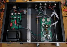
Thank you all for your insights and Jack for the boards. Went with a roomier store case per suggestions and a mu-metal divider to keep those nasty fields at bay.
A very nice addition to the F4 and MoFo amps I have constructed. I have recently completed the AKSA Lender preamp with higher gain daughter boards. So a listening session with the Pass diy BA-3, Sy's ImPasse and Hugh's AKSA Lender preamps driving the F4s seen in the photo will be forthcoming.
Regards to all,
David
Attachments

- Home
- Amplifiers
- Pass Labs
- ImPasse Preamplifier