Probably I’ve mentioned this too much, but I believe the Impasse and the Pass F-4 (which is what SY designed the preamp for) are one of the few successful “hybrids” combining tube in the gain stage and solid state output stage devices, which should combine the strengths of both but seldom do.
I did have noise issues in one channel but “bad tube” was generally dismissed as too obvious or something. The problem was exactly that.
I did have noise issues in one channel but “bad tube” was generally dismissed as too obvious or something. The problem was exactly that.
Last edited:
Probably I’ve mentioned this too much, but I believe the Impasse and the Pass F-4 (which is what SY designed the preamp for) are one of the few successful “hybrids” combining tube in the gain stage and solid state output stage devices, which should combine the strengths of both but seldom do.
Any chance we might see pcbs in the store? Ive been trying to get a set for years already
")
I'm surprised no one else has commented on your guts in deciding to cram both of these in one chassis, or on the build quality you've demonstrated. Great stuff!
Thanks! I wasn't too brave. If the high voltage trafo had caused noise, I would have still needed the 4U for its big heatsinks. I would have just made an enclosure for the tube psu and rearranged things in the 4U.
Any chance we might see pcbs in the store? Ive been trying to get a set for years already
You can get Impasse boards from Jackinnj, the OP of this thread. Those are the boards I used and they are well designed and work fine. I also bought the Impasse power supply board and Cinemags from Jackinnj.
I think that mrdave45 built his with single ended output, as I did. With my speakers, I don't see a need for more power, but the Impasse was designed for balanced output and 2 F4's. I don't know how many others built with balanced output, but expanding on Variac's comment, it is a surprisingly good hybrid that gives excellent results with both single ended and balanced output. A really remarkable achievement.
Jac
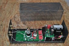
In 2013 I also built an Impasse Preamp for use with an F4, but I built in a separate enclosure, as shown below. My experience was also that the sound changed significantly with different tubes. With the right tubes the Impasse+F4 provided very pleasant listening experience.
I found that some tubes had bad levels of hum, or hiss. One tube, a Hytron 6SN7GT, had very bad hum in one triode. There was a CBS Hytron 5692 that I had for a short period that produced beautiful sound.
I found that some tubes had bad levels of hum, or hiss. One tube, a Hytron 6SN7GT, had very bad hum in one triode. There was a CBS Hytron 5692 that I had for a short period that produced beautiful sound.
Attachments
It Did What?
I am hoping you experienced tube guys can explain something for me. Maybe even suggest what I should do.
My initial build of the Impasse came out with Vgk being higher than target from the article. So I have gone back to tune the voltage divider made by R8 and R9. Specifically, I have been adjusting R8 and leaving R9 alone at 1 Meg.
The plate voltage at the 6SN7 is constant at about 150 VDC. B+ is also constant at 357 VDC. Because the grid and neon (below breakdown) are very high resistance, I assumed that the R8/R9 voltage divider would act independently of Vk on the 6DJ8. That's not what I am finding. As I decrease R8, increasing Vg to ground, I find Vk to ground also increasing or said another way, the voltage across the tube Vak is dropping and the current through the tube is increasing.
To cite two examples on either end of the spectrum;
With R8 at 120k, Vg to ground is 133 V and Va to ground is 136 for a bias of -3 V and 9.1 ma Ia based on voltage across R12. Va across the tube is 85 V.
With R8 at 470k, Vg to ground is 99 V and Va to ground is 106 for a bias of -7 V and 7.1 ma Ia. Va across the tube is 145 V.
The trouble is that when I try to plot the operating point, 85 Va and -3 Vg is barely above cutoff and only showing 1 ma not 9 ma. Clearly I am doing something wrong.
Looking at 470k is even worse. 145 V is deep in cutoff for anything like a bias of -7.
The fact that the amp played at all with a bias of -4.5 V clearly lets me know that I am doing something wrong. Should I just ignore the plot and keep going to a bias of -2 V and more than 9 ma?
Even more helpful, if someone can explain the right way to look at this, I would be grateful. I have been trying to find the answer in Morgan Jones, but no success so far.
Thanks in advance.
Jac
I'm having a lot of difficulty following what is going on. I am not sure what you mean by Va - is this the voltage at the anode as is convention or somewhere else like the cathode as I infer?
I am not sure why you are doing what you are doing, the values given are guidelines, and could be off 10% or more depending on the tubes used.
I would probably just use an R8 close to the value SY originally recommended.
If you have 80 - 100V across the plate to cathode in the 6DJ8 you should be in approximately the right area.
Note that if you are measuring the voltage at the grid of that 6DJ8 it is pretty likely the meter is loading down the relatively high source resistance of the divider circuit and giving erroneous lower than actual readings.
I'm having a lot of difficulty following what is going on. I am not sure what you mean by Va - is this the voltage at the anode as is convention or somewhere else like the cathode as I infer?
I am not sure why you are doing what you are doing, the values given are guidelines, and could be off 10% or more depending on the tubes used.
I would probably just use an R8 close to the value SY originally recommended.
If you have 80 - 100V across the plate to cathode in the 6DJ8 you should be in approximately the right area.
Note that if you are measuring the voltage at the grid of that 6DJ8 it is pretty likely the meter is loading down the relatively high source resistance of the divider circuit and giving erroneous lower than actual readings.
Hi kevinkr,
Thanks for answering. I am using Va as the voltage across the tube, anode minus cathode. For the bias, I am using the voltage of the grid above ground minus the voltage at the cathode above ground.
Your point about the voltmeter is a good one. I have been measuring with my Keithley bench meter that has 10 Meg input resistance on the voltage range measured here.
I got into this because SY's article said he wanted about 110 volts, 8 ma across the tube (anode to cathode) with the cathode 120 volts above ground and the grid at 118 volts for a bias of -2 V.
Using SY's resistor values, I measure 169V across the plate to cathode, 6.3 ma across the cathode resistor, and a bias of -8.2V. Looking at the datasheet (Ia versus Va plot) a Va of 169V and a bias of -8V is down on the Ia equal zero line. Obviously, I'm doing something wrong in my measurements because SY would never put the operating point in the cutoff.
Maybe your right. Maybe I should just accept that I am doing something wrong and use SY's resistance values. That is certainly easy.
Ok, I'm following a bit better..
The 10M of the meter is actually causing a small but likely significant error at the grid, I would estimate several % depending on the resistor values in the divider without doing the math.. (I'm feeling lazy at the moment)
If you can measure both the grid and cathode simultaneously you will get a more accurate result.
I would not tune the circuit to individual tubes in any event, but I would definitely check with a few other samples.
I'm assuming that there are no (or not so) obvious build errors. My recollection is SY liked and used JJ ECC88 in his builds so you might want to try a couple of these and see what if any effect this has. The '88/6DJ8 has fairly high slope transconductance (for a tube that is) and small changes in grid voltage may have surprisingly large effects on op point.
I think they're 0.01uf 600v ceramic disc, probably x rated (although I don't think they have to be, probably just because 600v caps are often like that) they're decoupling on the elevated heater supply, have a look here:
The ImPasse Preamplifier
The ImPasse Preamplifier
Another couple of questions from folks using Jack's boards. Referencing Jack's board, where does one connect the 6.3vac heaters? I think I would connect at the two side by side holes at the top of the 6DJ8 between R11 and R25. Just want to confirm.
Since the Allied transformer in the original build is no longer available I went with a Hammond xformer (272X). It does not have a center tap 6.3vac. Just 6.3vac on two wires. Will using this cause me difficulties? or ........
Thanks
David
Since the Allied transformer in the original build is no longer available I went with a Hammond xformer (272X). It does not have a center tap 6.3vac. Just 6.3vac on two wires. Will using this cause me difficulties? or ........
Thanks
David
You won't be able elevate the heaters without the centre tap. This will most likely result in more noise and/or hum. I'm not sure whether the design requires the heaters elevated to avoid damaging the tubes. Some designs you do need this other not. If you get hold of a 2x3.15 tx (wire like a dual rail supply and stick the elevated supply on the 2 wires you connected together, this is now your centre tap) or 6.3v ct tx of suitable current you could use that instead just for the heaters.
Another couple of questions from folks using Jack's boards. Referencing Jack's board, where does one connect the 6.3vac heaters? I think I would connect at the two side by side holes at the top of the 6DJ8 between R11 and R25. Just want to confirm.
David
Can't you just do a continuity check with the DMM between those points and the tube socket heater pins? Rather than trust a reply that may or may not be correct?
Jan
I think the heater supply wants to be balanced for emi suppression and connecting one side would send this off kilter. Check this page out
The Valve Wizard
It looks like you can create an artificial centre tap.
The Valve Wizard
It looks like you can create an artificial centre tap.
I think the heater supply wants to be balanced for emi suppression and connecting one side would send this off kilter. Check this page out
The Valve Wizard
It looks like you can create an artificial centre tap.
That depends on a lot of things, for example the heater inside the tube may or may not be symmetrical against the cathode.
Anyway, there is no reason a non-CT heater winding cannot be elevated and that was the issue.
And, as you say, you can always create an artificial CT with a pair of low value resistors.
Jan
- Home
- Amplifiers
- Pass Labs
- ImPasse Preamplifier