Late Again
Hello All,
As usual, I'm late to the party. I have just been catching up on this design and, as usual, I find myself attracted to Stuart's clean and logical approach. I know this is a several years old, but do there happen to be any boards available?
Nope, I'm not holding my breath. Blue is my natural color.
Jac
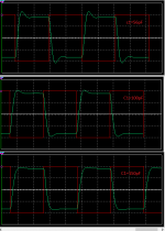
Luvdunhill, finally got to playing with loading of the Cinemag. With a 25k pot across the secondary, a Zobel of 330pF in series with 10k reduces the ringing to 5% and less than a cycle, well-damped (i.e., barely overshooting).
I will admit that I am still working my way through the whole thread, but I am 2/3 of the way home. I will be building using the Cinemags.
SY - How sensitive to capacitor value did you find the Zobel? I ask because I have some nice PS 430 pF in the drawer that I would try along side the 10k resistor, if it wasn't critical.
Thanks.
Jac
Tune the input impedance with a variable capacitor and potentiometer on the trafo secondary. Square wave and scope.
If you look at some of the tube preamp reviews in the trade publications, those that publish data and pix, you'll wind up saying to yourself "what were these guys thinking?"
If you look at some of the tube preamp reviews in the trade publications, those that publish data and pix, you'll wind up saying to yourself "what were these guys thinking?"
Hi Jac,
SY hasn't been seen around recently.
I wouldn't use a nice polystyrene capacitor for a zobel. They are too sensitive to heat for one. Try something that has higher current ratings, like a polypropylene that are used for snubbers or power applications.
-Chris
Hi Chris,
I suspected SY wasn't around, but didn't know for sure. I wish him well.
Ok, I'm always up to learn something new. I wouldn't have thought high current would have been a problem here. Impedances around it are pretty high and the signal level is pretty low. Even in resonance, I wouldn't have imagined a current issue. What am I missing?
Also, I would have thought this cap is close enough to the signal path that a nice cap would be a good thing.
Jac
Tune the input impedance with a variable capacitor and potentiometer on the trafo secondary. Square wave and scope.
Jack,
This is my first time working with input trafo's and part of my interest in trying this project. I have a couple of questions on how to set up this test.
- Test the trafo and Zobel only, or should it be "in circuit" and if so, powered or not?
- I've read 10k Hz square wave, but what amplitude should I use? or several amplitudes?
- My function generator has an output impedance of 50R, but my source output impedance varies from 250R to 380R. Having never played with output impedance before, do I just add 200R in series with the output of the function generator?
Thanks in advance.
Jac
Thank you both Chris and Jack. You have helped me better understand and I will do the experiment.
My plan is to use the Impasse as a front end (voltage gain stage) to the F4. That means no selector switch and no volume control, P1. I already am using a Reliaxed 2 preamp which is a nice balanced pre using a stepped attenuator made from discrete resistors controlled by relays.
My thought is to replace P1 with a 100k resistor with a direct connection from the top of the resistor to R3. I thought I should keep the impedance the same as SY's version running at full volume. Am I thinking about this correctly?
Also, I am presently planning on putting both the Impasse and the F4 in a 4U enclosure. I will be running balanced into the Impasse and single ended out to the F4 because I will only have a single, stereo F4. Should I be concerned about the high voltage AC in the same box as the F4? Naturally, I will twist wires, etc.
As a sidebar, the Impasse/F4 combo should actually be about 4 dB less gain than my current setup, so I'm not too worried about gain structure noise.
Jac
Also, I am presently planning on putting both the Impasse and the F4 in a 4U enclosure. I will be running balanced into the Impasse and single ended out to the F4 because I will only have a single, stereo F4. Should I be concerned about the high voltage AC in the same box as the F4? Naturally, I will twist wires, etc.
Don't forget that the 100k pot is in parallel with 1Meg, so effectively one 9.1k resistor would suffice.
On the board I sent you have the option of putting a balance potentiometer. Just trace your way to the top and bottom of the trafo secondaries.
OT Interesting Prices
It's been 8 years since this thread started and it's interesting to see how prices have changed over that time. At the time, the Allied power transformer was about $30 and the Cinemag input transformers were $35. Today, the cheapest power transformer I could find in the US is a Hammond for $80. One interesting thing is that surplus or "vintage" transformers were more expensive than new. The Cinemags are up to $70. On the other hand, I have been sourcing resistor for really cheap prices. One was only a penny.
If you ask the government, they will tell you that inflation was about 1% per year over that period.
I wondered if the price of copper had driven up transformers in general. Although copper is somewhat higher price than the lowest price, it is generally cheaper than it has been for the period before 2009 and since the dip.
My guess is that things like 650VCT transformers have become low volume and the makers are making us pay for our hobby. I'm not complaining. I chose this hobby and want the specialized parts. I just find it interesting.
Jac
Anyone else build without a volume control?
If anyone built without a volume control, did you experiment with the resistance value that replaced P1? If so, what differences did you find and what value did you choose?
It's time for me to show my tube ignorance.
I've been reviewing SY's bandwidth calculations in the article and,from the text, he is assuming the volume control is at mid-point. Looking into the circuit from the output of the input trafo's, the 100k pot would be roughly 50k. Combining that with the stated 80 pF of the 6SN7 tube, it gives an upper bandwidth limit of about 40 kHz, assuming I did the math correctly.
The tube spec sheet says typical grid to plate capacitance of 3.8 pF, which gives a Miller capacitance of 80 pF, so I guess this is the figure SY is working with. This makes some sense with the input on the grid and the output on the plate.
I'm a little surprised that "input capacitance - grid to cathode" isn't used for bandwidth since that is bypassing the input to ground at high frequencies. That would be nice since the grid/cathode has lower capacitance and is even in series with the LEDs.
With a fixed resistor instead of a pot, you can see how I would be tempted to try a lower input impedance. The Cinemags seem happy down to 10k. My source has an output impedance of about 270R, so I could have a decade ratio at 27k and I might stretch it as far as 22k. 27k gives a bandwidth of 74 kHz and 33k gives 90 kHz. Actually, the 5692 I plan on using has a little lower capacitance and would get me to 100 kHz.
I would appreciate any comments on my thought process, huge logic errors, math issues, appropriate values, or what you would do in my shoes.
Thanks in advance.
Jac
I'm a little surprised that "input capacitance - grid to cathode" isn't used for bandwidth since that is bypassing the input to ground at high frequencies. That would be nice since the grid/cathode has lower capacitance and is even in series with the LEDs.Jac
I missed the edit window. Looking a bit online, I was able to confirm that this quote above is the wrong way to look at it. I assumed SY knew what he was talking about and, of course, he did it correctly. I just haven't learned everything I need to know yet.
")
Jac
Impasse Input Impedance
I'm not clear on why SY chose to use a 100k volume pot paralleled with a 1M resistor on the input of the Impasse. I'm sure he had a good reason, although it might have been as simple as he had an available 100k pot.
I've been trying to understand the tradeoffs and thought I would share what I have learned. Please correct any errors or lack of understanding.
The tradeoff is that higher input impedance decreases the bandwidth through the tube due to Miller capacitance while at the same time increasing the bandwidth through the input trafo. There is also a small secondary effect on the trafo where the distortion increases slightly.
If you look at the Cinemag datasheet, they show both the bandwidth and distortion at 10k and 15k load for the trafo. You will note that this is much lower resistance than we typically use as input impedance. From the datasheet, the CMLI-15-15B has an 3 dB down point of 60 kHz at 10k and 80 kHz at 15k. At those same loads, the Miller capacitance based bandwidth would be 200 and 130 kHz respectively. Since my personal target would be a 100 kHz bandwidth, it looks like there should be a sweet spot between 15k and the 100k pot, assuming the trafo bandwidth trend continues at higher load impedance.
I contacted Cinemag and they gave me a quick and friendly reply. They said that they had tested the CMLI-15-15B at 18k load and the bandwidth continued to increase. Beyond that, they get worried about the extra loading of the input cables, even short cables.
If I assume that the bandwidth increase linearly with load (unlikely, but all I can assume given two points), then 18k would give bandwidths of 92k and 110k for trafo and Miller respectively. Pushing it to 20k gives 100 kHz bandwidth for each.
From the datasheet, the CMLI-15-15B adds about 3k of impedance to the input impedance of the preamp. That means that an 18k load would offer 21k of input impedance. A side effect of this is that a lower load resistance would lower the voltage at the 6SN7's grid input. In effect, this would be reducing the gain of the preamp. Using vastly simplified assumptions, I tried to estimate this. Compared to the mid point of a 100k pot, an 18k load resistor is estimated to drop the gain by about 1/2 dB.
I would love to test this personally in the Impasse circuit, but my sound card based measurement system won't do 100 kHz. Instead, I will try some different resistances subjectively to see if I can even tell the difference. Naturally, this changes everything with the input zobel.
Im still getting the fizzing sound though. However this is back to the situation where the volume pot is not affecting it.Thanks
Mr. Dave,
Were you able to solve your fizzing noise issue? If not, I have one more area to suggest you might check.
About a year ago, I was building SY's Eq. OPP phono preamp which uses the same CCS design as the Impasse. At the time, I had a similar noise problem that ended up being an unusual problem with the DN2540 mosfets.
At present, I am building the Impasse and just got my batch of DN2540's for that project. In matching, I found the same problem on 2 or the first 12 parts I tested.
The problem is that the DN2540 behaves normally at Vgs and above but won't shut off at more negative voltages. In my test rig, I am measuring drain current and Vgs using two meters. With a good DN2540, drain current drops to zero (or less than my mA meter can read) and stays at zero as Vgs becomes more negative. With a "bad" DN2540, drain current will drop down to about 0.1 mA, then increase as Vgs goes further negative. In the case of my phono pre build, this was the cause of my "fizzing" noise.
I had a hard time finding this problem because I wouldn't have normally looked lower than Vgs. I ended up having to use a 9V battery as a secondary voltage source so I could individually control Vgs.
As for DN2540's, it looks like Microchip is having a quality issue based on me finding problem parts in 2 separate batches. I hope this info is helpful for you.
Jac
- Home
- Amplifiers
- Pass Labs
- ImPasse Preamplifier