Hi Everyone
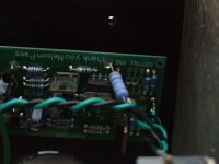
I recently picked up a used Pass Aleph clone amp. The boards are laid out like the F series - a long thin circuit board an each side and a central power supply board. On the circuit boards the following info is printed : upper left hand side has Aleph clone and on the lower left 327791 Thank you Nelson Pass.
This little guy appears to have been built on a very tight budget. I'm mainly looking for power supply requirements as it's likely the transformer is marginal at best. I would love it if you can direct me to any further info as well. I went through all the Aleph stuff here and on the Pass site. I could not find anything with picture of the boards that looked right.
Any information would be greatly appreciated.
I was going to get in on the group buy for the F3,4,5 series Peter Daniel has going, but as I tinker with this little rascal the more I like it. I'm starting to question whether to get involved with an F series build. (plus I'm amassing parts towards a TubelabSE 300B project so I want to allocate my toy money as wisely as possible.)
Thanks
Kevin Bown
Hi
While I try to figure out how to post a picture I'll give you the following information.
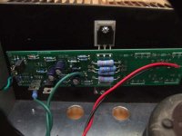
The Voltage coming onto each circuit board is 35VDC.
The power supply has 8 x 2200uF caps and a single bridge rectifier is used ( 35.9VDC @ the rectifier)
The output fets are TO220 style Fairchild 19V20C 200V N mosfet.@ 2 per board.
I'm borderline ingnorant as far as electronics go so I don't want to poke and prod anything more than that without a schematic or advice on what/where to check.
thanks
Kevin
While I try to figure out how to post a picture I'll give you the following information.
The Voltage coming onto each circuit board is 35VDC.
The power supply has 8 x 2200uF caps and a single bridge rectifier is used ( 35.9VDC @ the rectifier)
The output fets are TO220 style Fairchild 19V20C 200V N mosfet.@ 2 per board.
I'm borderline ingnorant as far as electronics go so I don't want to poke and prod anything more than that without a schematic or advice on what/where to check.
thanks
Kevin
brownie said:Hi
While I try to figure out how to post a picture I'll give you the following information.
The Voltage coming onto each circuit board is 35VDC.
The power supply has 8 x 2200uF caps and a single bridge rectifier is used ( 35.9VDC @ the rectifier)
The output fets are TO220 style Fairchild 19V20C 200V N mosfet.@ 2 per board.
I'm borderline ingnorant as far as electronics go so I don't want to poke and prod anything more than that without a schematic or advice on what/where to check.
thanks
Kevin
send pictures to me , and I'll shrink them and post ;
>choky@neobee.net<
Are you sure the output devices are TO-220 and not TO-247?
to-220 devices are not up to the job for a power amp, especially with 36vdc rails.
What size are the heat sinks (H-W-D)?
You can upload a digital picture to a thread up to 102K in size. Take a picture in the lowest resolution for your camera. I use 640x480 resolution for attaching pictures here.
-David
pics
2/2
judging by round holes in bottom plate .... and few other things - possibly Rawson's work
with just two mosfets ( TO247) per channel and aroound 40Vac across graetz- you're in Aleph 30 area ...
put more caps for starters ;
adding one more pair of outputs per channel can be wise , but you must match new ones , and just hope that old ones from one channel can put on other channel , as matched
Attachments
Hi Kevin,
I agree with with Choky that it's an Aleph that could have been better built.
If the board was mine, I'd either install more output mosfet's or bring down the voltage and bias. Consider installing 2 sets matched triplets of IRFP9240's for each channel. It also looks like the protection diodes are missing. This is not a big deal but you do run a risk of blowing the input mosfets if the input source cables are plugged in or pull out when the amp or source is turned on.
An Aleph 30 has about 25 volts at the rails and an Aleph 60 has about 35 volts. Those heat sinks don't look like they can dissipate 200 watts, but maybe 100 for the A30.
Nelson has a good DIY heat sink test. After the amp has warmed up, place your hand on the top of the heat sink. If you can keep your hand there for 5-7 seconds without it getting uncomfortable, the heat sinks are dissipating about 150 degrees F. This should be an absolute max for generated heat.
John here on the board sells matched mosfets and a good guy to work with. http://www.tech-diy.com/Store/Hexfets.htm
John can sell you the matched devices.
I also agree with Choky's suggestions regarding construction.
-David
One other suggestion, place a large washer with a small hole between the output mosfets and the head of the mounting screw to ensure even pressure of the device to the heat sink. Spreading out the pressure not only helps with heat distribution, but also helps to keep the mosfet from cracking.
-David
-David
@David
I preume that that amp - with weeny 40ct Vac xformer and just 8x2200uF , can't be above Aleph 30 PSU voltage ;
@brownie :
can you give us more pictures ?
what's xformer make/type ?
maybe you can buy same one , and wire two of them as monoblock PSUs ;
you can look at apexjr.com for dirt cheap and adequate caps ; buy lots of them , and put in .
Hi
I'm just going by what Fairchild posted on their info sheet for that part number. I could be COMPLETELY wrong -As I said I'm a world class idiot when it comes to this stuff.
Zenmod has stepped in and is helping getting pics posted.
The heat sinks are part of the case itself and measure 10 inches long by 4 1/2 inches high with the solid portion of the metal prior to the fin extrusions starting is 3/8" with the entire thickness of the fin being 1 and 1/2 inches. The top plate of the case gets the warmest but it still isn't beyond hot to touch after an hour or so of running The sinks themselves aren't very hot at all- I've immediately picked the amp up by the heat sinks and carried it to another room after running for 2 hours.
Another bit of weirdness- the transformer is an RS Components Model 208-125. On the sticker it has Pri 125-125V and 15-15 V secondary 4A max per winding.
It would appear it's putting out 120% of rating -way more than spec - is this normal for transformers? I've read the power supply trannies Hammond puts out which are suitable for 300B tube gear are very prone to this.
Those measurements were taken dead cold with in a minute of turn on.
I let it run for about 15 minutes and checked it again and both circuit board inputs read 35.0 VDC
The truly odd part is how good it sounds. It's a testament to the designing skill of Mr Pass - you can have an awful execution and it still sounds great.
Thanks for taking interest in my issue here.
Kevin
Hi Again
Zen mod posted the pictures ( thanks very much!!) while I composed the last reply. Thanks for giving me a lead on this guy's identity.
I hate to say it but the majority of the wire has already been cleaned up - you should have seen it before I went in and re-did some. I wish I had taken a picture....... I need to redo the output wire but I was waiting on the outcome of this before taking the power supply board off and mucking about.
Do you have any cap amount in mind? Would I simply be able to use larger caps on the same spot or get another power supply board and use 2 bridge rectifiers ?? Bypass caps a good idea ?( I have a bucket full from a different amp rebuild 0.47 uF /400 Volt auricaps)
For the application - it is for a Fostex FE207E/Ft17H Half Chang high eff. speaker so I already have more than enough power.
Thanks for all the help guys
Kevin
Hi Kevin,
You are probably measure + to - resulting in 35vdc rather than + to ground for a value of probably 17vdc. The PSU is most likely +-17vdc. Double check this by measuring + supply to ground.
The heat sinks size you describe as 10x4.5x1.5" with a 3/8" base is a good heat sink for this power and maybe even slightly undersized.
You are probably OK with the amount of output mosfets if the rail voltage is +-17vdc. Personally I would have used 2 mosfets per side per channel to provide a larger operating margin. This is a guess given the amount of information provided.
-David
go there : http://tiny.pl/ngd2
look for Nichicon 12000uF/50V snap in caps
buy as much you can , maybe even for later use , if you're infected with disease which grab us all")
seems that you have sort of Mini Aleph , resuming that you actually have +/- 17V5 going to pcbs
anyway - can you find what specs are for that xformer - looking at RS site ?
besides that - measure what's voltage across these 0,33R resistors , then we will know what's Iq through output stage ........ and dissipation .
give us few more pics , from different angles and plans ; then we can think more , how to improve little fella
look for Nichicon 12000uF/50V snap in caps
buy as much you can , maybe even for later use , if you're infected with disease which grab us all
seems that you have sort of Mini Aleph , resuming that you actually have +/- 17V5 going to pcbs
anyway - can you find what specs are for that xformer - looking at RS site ?
besides that - measure what's voltage across these 0,33R resistors , then we will know what's Iq through output stage ........ and dissipation .
give us few more pics , from different angles and plans ; then we can think more , how to improve little fella
Hi
Thanks again for the suggestions
I'm at work but will try to get the info you asked about later this afternoon evening.
The transformer is a now discontinued item with no information left at the site.
Seems to me it may be just as well to get a new power supply transformer.
We have a couple very good electronic supply outlets here in town so I'll see if they carry or can get the caps and look into those matched Output Fets.
Thanks
Kevin
brownie said:Hi
Thanks again for the suggestions
I'm at work but will try to get the info you asked about later this afternoon evening.
The transformer is a now discontinued item with no information left at the site.
Seems to me it may be just as well to get a new power supply transformer.
We have a couple very good electronic supply outlets here in town so I'll see if they carry or can get the caps and look into those matched Output Fets.
Thanks
Kevin
improving path :
1. PSU caps ( more of them )
2. xformer issue
3. output mosfets
>3.< isn't big deal if you are satisfied with power ; we'll know more when you post results of asked measurement
Hi Again
Measurements- Yup I'm dumb, when you measure from ground to the + lead onto the board it's 17.5 VDC on both sides.
I hope I did the resistor values at the correct place -it appears to be 0.4 V drop across the resistor.
The caps - they'll have to be ordered on line -the local guys don't want to do onesy twosy in non stock items and they can't do close match fets.
Hope this is what you need if not I'll measure some more
thanks
KB
Hi
I'm really starting to wonder if I'm measureing the right resistors for you. I have a cheap meter so accuacy may not be great 17.49 -17.05 on 33 and the '0" has 0.04 on either side.
Thanks for the heads up on the source for the caps I'll get on it. Nah shipping is just a fact of life these days. I'll likely order a power transformer on line too.
Thanks
KB
- Status
- This old topic is closed. If you want to reopen this topic, contact a moderator using the "Report Post" button.
- Home
- Amplifiers
- Pass Labs
- Aleph clone ID