Hello,
I'm building a pair of F1's over the holiday break. Below are pictures of the main Amp board.
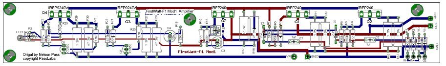
I'm looking for advice on these boards and any helpful input to improve the layout. This is a single sided board with all traces on the bottom layer and a ground plane on the top layer.
The board is 2"x6.5" or for our friends elsewhere in the world... 50.8mm X 165mm. The top layer silk screen is imaged here on both sides to help facilitate design ideas and perhaps catch any errors.
Thank you!
-David
Bottom layer looking through the top:
Top View:
I'm building a pair of F1's over the holiday break. Below are pictures of the main Amp board.
I'm looking for advice on these boards and any helpful input to improve the layout. This is a single sided board with all traces on the bottom layer and a ground plane on the top layer.
The board is 2"x6.5" or for our friends elsewhere in the world... 50.8mm X 165mm. The top layer silk screen is imaged here on both sides to help facilitate design ideas and perhaps catch any errors.
Thank you!
-David
Bottom layer looking through the top:
An externally hosted image should be here but it was not working when we last tested it.
Top View:
An externally hosted image should be here but it was not working when we last tested it.
Here's the BOM for this F1:
An externally hosted image should be here but it was not working when we last tested it.
Closer to actual size 2.0"x6.5" ... -David
An externally hosted image should be here but it was not working when we last tested it.
I'm no expert, but those FETs look awful close to one-another to me...
Unless you're doing liquid freon cooling or something, think you want an inch or more between them to allow them space to cool (depending on thickness of heatsink base & other characteristics.)
They get mighty hot Others may be able to be more specific.
You are probably trying to reduce PCB area due to cost, but something more like 9"x1.5" might make a better home for your FETs.
Re: Ground plane - Didn't have one on my F1 boards, didn't use them on the F2 boards I ExpressPCBed & still dead quiet on my FE126s. But again, no expert here.
Maybe you should share your heatsinking ideas to get feedback from some on that too")
Unless you're doing liquid freon cooling or something, think you want an inch or more between them to allow them space to cool (depending on thickness of heatsink base & other characteristics.)
They get mighty hot
Others may be able to be more specific.You are probably trying to reduce PCB area due to cost, but something more like 9"x1.5" might make a better home for your FETs.
Re: Ground plane - Didn't have one on my F1 boards, didn't use them on the F2 boards I ExpressPCBed & still dead quiet on my FE126s. But again, no expert here.
Maybe you should share your heatsinking ideas to get feedback from some on that too
Very nice work David
It looks like you could push the device spacing out if you wanted.
Did you originally do a single-sided layout? It looks like it would be a simple thing to make it single sided - would you mind if I used your artwork as a basis for my own? You don't have to send or post anything - I'll draw my own layout for etching but will modify for single sided.
Thanks for sharing and thanks to Nelson for being the first one to share 
F1 is the only one I haven't started building (F4 and F5 running, F2 and F3 partially populated)
It looks like you could push the device spacing out if you wanted.
Did you originally do a single-sided layout? It looks like it would be a simple thing to make it single sided - would you mind if I used your artwork as a basis for my own? You don't have to send or post anything - I'll draw my own layout for etching but will modify for single sided.
Thanks for sharing and thanks to Nelson for being the first one to share
F1 is the only one I haven't started building
(F4 and F5 running, F2 and F3 partially populated)F1 Boards
Thanks for the input. I've redrawn the boards to a width of 9"x2" to spread out the the mosfets for better heat distribution.
Here is version .92
After a little more feedback, I'm placing an order. Does anyone else need F1 boards?
-David
Bottom layer looking through the top:
Top with Silkscreen:
Approximate actual size:
Thanks for the input. I've redrawn the boards to a width of 9"x2" to spread out the the mosfets for better heat distribution.
Here is version .92
After a little more feedback, I'm placing an order. Does anyone else need F1 boards?
-David
Bottom layer looking through the top:
An externally hosted image should be here but it was not working when we last tested it.
Top with Silkscreen:
An externally hosted image should be here but it was not working when we last tested it.
Approximate actual size:
An externally hosted image should be here but it was not working when we last tested it.
Re: F1 Boards
Sure, I would take some boards, but where is C3 1000uf cap gonna go? Is it hiding on me?
dw8083 said:Thanks for the input. I've redrawn the boards to a width of 9"x2" to spread out the the mosfets for better heat distribution.
Here is version .92
After a little more feedback, I'm placing an order. Does anyone else need F1 boards?
-David
Bottom layer looking through the top:
An externally hosted image should be here but it was not working when we last tested it.
Top with Silkscreen:
An externally hosted image should be here but it was not working when we last tested it.
Approximate actual size:
An externally hosted image should be here but it was not working when we last tested it.
Sure, I would take some boards, but where is C3 1000uf cap gonna go? Is it hiding on me?
F1 Boards
Thanks mithomas, I fixed the C3 cap.
Below is version .93 of the boards. I'm hoping to find enough DIYer's for 10 or more boards for a small GB. 30 boards are $18.00 each, 40 boards are $15.00 each
- plus shipping which is probably a buck in the US for a pair of boards. If we have enough interest, I'll get approval from Nelson to proceed.
The boards are 0.062" FR-4 epoxy glass, double sided, green solder mask on both sides, and with a silk screen on the top layer.
The copper traces are 1 1/4 oz. Dimensions are 2"x9" or 50.8mm x 228.6mm.
The top layer is a ground plane.
I appreciate any additional error checking or thoughts or challenges to the layout to improve it.
-David
Bottom Layer looking through the top:
Top layer with Silk screen:
Thanks mithomas, I fixed the C3 cap.
Below is version .93 of the boards. I'm hoping to find enough DIYer's for 10 or more boards for a small GB. 30 boards are $18.00 each, 40 boards are $15.00 each
- plus shipping which is probably a buck in the US for a pair of boards. If we have enough interest, I'll get approval from Nelson to proceed.
The boards are 0.062" FR-4 epoxy glass, double sided, green solder mask on both sides, and with a silk screen on the top layer.
The copper traces are 1 1/4 oz. Dimensions are 2"x9" or 50.8mm x 228.6mm.
The top layer is a ground plane.
I appreciate any additional error checking or thoughts or challenges to the layout to improve it.
-David
Bottom Layer looking through the top:
An externally hosted image should be here but it was not working when we last tested it.
Top layer with Silk screen:
An externally hosted image should be here but it was not working when we last tested it.
grimberg said:Regarding your BOM, I suggest you purchase Vishay/Dale resistors and Wima capacitors from Mouser. They carry both MKP and FKP. If you search the forum you will see that some members have had issues with the vendor you have selected.
Thanks grimberg. I've updated the BOM in Post #2 to remove Welborne and use Mouser instead.
-David
Here's the final board design, unless there's an idea for improvement.
For a GB so far:
2 channels mithomas
4 channels for Mega-Amp
4 Channels for DW8083
Bottom Layer looking through the top w/silkscreen shown for reference:
Top layer with Silkscreen:
For a GB so far:
2 channels mithomas
4 channels for Mega-Amp
4 Channels for DW8083
Bottom Layer looking through the top w/silkscreen shown for reference:
An externally hosted image should be here but it was not working when we last tested it.
Top layer with Silkscreen:
An externally hosted image should be here but it was not working when we last tested it.
Random thoughts
my opinion would be to take out the LED pot control, and leave a fixed resistor there. That would be net cost savings, and shows some effort in not copying Nelson's design.
It's only an opinion however.
If you ask Nelson personally, he is usually quite obliged.
Before going to the group buy section consider the following -
1- We gotta make sure the circuit works! Of course it wont hurt to get an idea of interest via a WIKI.
With the F3-F5 series that I helped setup and PD is executing - There is a donation towards DIYAudio from each board sale. Same for the Toolereg group buy. It's a good way to keep the site up , in potentially difficult times. Even a dollar a board or something would be cool with me.
I know in the F3-F5 PCB group buy, there have been some wanting to buy the F1-F2 as well.
I have build the F2 P2P and is a very interesting amp. Like all of them IMO, take a long time to warm up though....
Thank you Nelson. You are indeed are a national treasure so generously lending your valuable resources, especially time, to encourage and help us learn about audio electronics.
I'm deeply appreciative and place you in my best thoughts for all you have done to bring additional happiness to my life - and reigniting my passion building hifi audio circuits.
Happy Holidays!
-David
I'm deeply appreciative and place you in my best thoughts for all you have done to bring additional happiness to my life - and reigniting my passion building hifi audio circuits.
Happy Holidays!
-David
dw8083 said:......You are indeed are a national treasure .......
what is with rest of us .....
 unfortunately members of other nations ........ ?
can we have piece of Papa , as our own national treasure ?
Attachments

- Status
- This old topic is closed. If you want to reopen this topic, contact a moderator using the "Report Post" button.
- Home
- Amplifiers
- Pass Labs
- First Watt F1 Build with boards