I was waiting for Papa's PCB to be available, but no news yet . . .
>> <<
<<
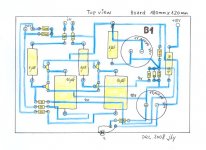
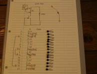
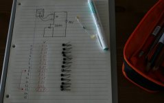
So, I will walk my way again with my blue color pen. The board size is 180mmX120mm. I could squeeze the size a bit. I will have neither the selector nor the volume because I have another independant box having six source selectors and 100K volume attenuator.
Any comment?
Cheers,
>><<
>>
<<So, I will walk my way again with my blue color pen. The board size is 180mmX120mm. I could squeeze the size a bit. I will have neither the selector nor the volume because I have another independant box having six source selectors and 100K volume attenuator.
Any comment?
Cheers,
>>
<<Attachments
Your hand drawn PCB's look like fun. I bought some pens and a nice big board to play with. I've just finished my first rough draft of a hand drawn Szekeres Headphone Amp PCB. I learned a few things on this and need to try again, but it should be a little easier next time. Your B1 has some aspects I had not thought of. You are making an effort to have equal length traces between some sections. I'll add that the list of things to keep in mind when laying out a PCB. I'm following your method from your "New-building of my F5" thread. Any breadcrumbs you drop along the way will be picked up.
Thanks
Jim
Thanks
Jim
JimT said:... an effort to have equal length traces between some sections...
You have eagle eyes . . .
I like to have the super-symmetric lenth of traces between L ch and R ch about the ground point. I do not know exactly this would have any meaning. But, who knows? The devil might be existing in the small detail . . . ?
Cheers,
>>
<<Zen Mod said:led legs aren't squared

hehe
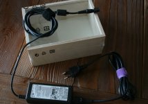
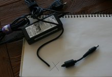
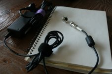
heheI'm going to use the computer AC adaptor for the power supply. It has the output of 19VDC 3.16A. Since the adaptor jack is too small sized for me to handle properly, I'm thinking of cutting off the plug part including the ferrite core and replacing with two pole connector which I could easily mount to the chassis.
Hmm . . . I'm also thinking of a wooden box B1 . . .
>>
<<Attachments
 <<
<<


steenoe said:... I have a board for you (if you want it), just needs drilling
Okay, let me try it. Many thanks
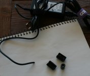
By the way, let me continue with the ac adaptor. Now the ferrite core has been re-installed on the line, and the two-pole mini connetor has been attached. Ready to be used . . .
Cheers,
Attachments
Hi Bab,
Wait, don't use those pairs just yet. Add 9 & 11 and 1 & 13 as possible candidates for matched pairs.
Set up an LTP jig and measure the tracking of the prospective pairs. If they are good then keep them for a specialised use that really benefits from matched pairs.
Now, pick two pairs with similar Idss (2% or 3% error is OK) for the B1, it does not need nor benefit from real matched pairs.
AndrewT said:
Add 9 & 11 and 1 & 13 as possible candidates for matched pairs.
I feel like a blind . . . How come I couldn't see 9&11 and 1&13?
>>
 <<
<<It's too late . . . I already chosen the marked four, and returned the others into the unmatched bunch with no marking because I always match them in different ways for the different purposes . . .
Cheers,
Re: Parts
I got some from Korean manufacturer (upto year 2000).
Some in Norway (year 2000-2002).
Some in China (year 2004-2007).
I like Chinese best. Very good price and quality.
>><<
enzedone said:Babo where did you get all those trannies from?
I got some from Korean manufacturer (upto year 2000).
Some in Norway (year 2000-2002).
Some in China (year 2004-2007).
I like Chinese best. Very good price and quality.
>>
<<
Babowana said:This morning I tried the second round of the matching test.
At about 10.5 Vds, four 2SJ170s having the following Idss finally chosen:
8.50 mA - 8.50 mA
8.67 mA - 8.68 mA
I hope these will well play their role . . .
>>
Just a suggestion;
You could also use number 2+11 and 9+3. With 2 and 9 as the top J-fet. Check out what was said here:
J-fet matching for B1
That would save you the 2 excact matching sets.
- Status
- This old topic is closed. If you want to reopen this topic, contact a moderator using the "Report Post" button.
- Home
- Amplifiers
- Pass Labs
- New-building of my B1 buffer