GL,
Thanks for the feedback. Jeff basically summed up the response I wanted to make, so I don't have much to add right now.
Right now I'm trying to source power supply capacitors, though I'm a bit confused by some of the things I'm reading:
"Do be sure that your power supply caps are rated about 20% higher than your planned rail voltage so that the caps can comfortably handle the voltage and to provide a safety margin. 25v caps are just fine for an amp with 21v - 22v rails."
by:
http://www.facstaff.bucknell.edu/esantane/movies/aleph-x.html
Yet, I read another view in Nelson Pass' Aleph 30 manual:
"The power supply has been improved with half-again more power supply capacitors with twice
the voltage ratings, giving lower ESR figures."
I guess I'm confused about ESR, it seems like as long as we stay within the voltage ratings and keep our caps in a reasonably cool environment we should be okay right?
I'm also looking for recommendations for brands/models and good places to buy them. Mouser had a nice looking Vishay, would this suit our purposes?
http://www.mouser.com/Search/ProductDetail.aspx?qs=edHq/kBWWx59rKz4VHziig==
That Vishay capacitor appears to be an excellent choice.
There are two voltage ratings for electrolytics. The first is the working voltage. This is the recommended maximum voltage at which you would design your power supply to run. The cap can take more than this for short periods. The second rating is the surge voltage. This is the voltage that you never want to exceed. Most of the cap manufacturers have app notes about this. Check out their websites. Bottom line is that I don't worry about using electrolytics right up to the rated working voltage.
Another thing to remember about aluminum electrolytics is that they "re-form" over time. If you use one at a lower than the rated working voltage then it will slowly re-form to that working voltage (and it's capacitance will rise). So it's always best to choose a cap that closely fits your requirements.
The ideal power supply supplies up to infinite current with instantaneous response. This is impossible. But people try to get as close as they can afford by using using big transformers, big low ESR caps, and the newer lower noise and low drop out diodes. All are good and they all make a difference. It comes down to cost. But I'm probably telling you stuff you already know.
Once again I think you have chosen an excellent cap.
In the AX100's I used IXYS DSEI60-06A diodes and after 3 years I would still pick these. Digikey has them.
Graeme
I heart resistors
Hi guys,
My buddy's girlfriend finally went back to Europe so we have resumed working on our PSU here....

We've put together an order for most of the components but had some difficulty choosing resistors.. yes this should seem odd.
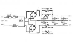
We are looking for 0.25 Ohm, 25 W resistors (as seen in the attached schematic). It appears that ceramic resistors are hard to find with such specs.
We found these power resistors:
http://www.mouser.com/Search/Refine...7642+4294575782&Keyword=0.25+resistor&FS=True
At almost 8 bucks a pop this seems a bit costly.
We have found there are several other options with metal wire wound resistors:
http://www.mouser.com/Search/Refine...7642+4294572354&Keyword=0.25+resistor&FS=True
but are worried about the inductance of these and question how it may affect the filtering capabilities of our current design (see attached schematic).
Our questions are:
Are there less expensive resistors that are suitable for our design?
and
If we use metal wound resistors, should we use the non-inductive type?
Thanks for your continued support!
Jeff...
Hi guys,
My buddy's girlfriend finally went back to Europe so we have resumed working on our PSU here....
We've put together an order for most of the components but had some difficulty choosing resistors.. yes this should seem odd.
We are looking for 0.25 Ohm, 25 W resistors (as seen in the attached schematic). It appears that ceramic resistors are hard to find with such specs.
We found these power resistors:
http://www.mouser.com/Search/Refine...7642+4294575782&Keyword=0.25+resistor&FS=True
At almost 8 bucks a pop this seems a bit costly.
We have found there are several other options with metal wire wound resistors:
http://www.mouser.com/Search/Refine...7642+4294572354&Keyword=0.25+resistor&FS=True
but are worried about the inductance of these and question how it may affect the filtering capabilities of our current design (see attached schematic).
Our questions are:
Are there less expensive resistors that are suitable for our design?
and
If we use metal wound resistors, should we use the non-inductive type?
Thanks for your continued support!
Jeff...
Attachments
A few comments
I did not read all the postings, but I have a couple of suggestions which you may or may not want to incorporate (perhaps you already have it in there but not on the schematics).
1. Always put some film capacitance across the electrolytics. It does not cost a lot of money and it helps a lot. You are worried about inductance of the series resistors - well check out the series inductance of the electrolytics alone!
2. Series inductance of the resistors - this is actually a good thing - it is not as if you are going after a low output impedance supply given that you are using series resistors. If you are concerned with this and would like to try to model it on the computer, I recommend PSUD2 - search for it on the Internet. Very handy to test your theories.
3. Why are you using resistors and not inductors - energy storage of an inductor is proportional to I^2 and you don't actually need to have losses at all (well you will have losses of course). My point is that you might want to consider inductors since you are going after high power Aleph - i.e high current and thus a lot of energy to burn over resistors. In fact, the right inductance in the right place (before the first big caps) can make your transformer look a lot bigger so don't laugh at it - the way it works is that it lengthens the charge pulses with many benefits but you stress the diodes more (need higher voltage ratings). The latter can be alleviated by putting a small high quality film C before the inductors + snubberizing the diodes.
As noted, just a few semi-random thoughts which might be of value during the information gathering process
Petter
- Status
- This old topic is closed. If you want to reopen this topic, contact a moderator using the "Report Post" button.