Ignore higher harmonics for a while, as they are all very small and are probably just FFT artifacts.
Looking at the lower harmonics there are two things going on:
1. slight rise in third order, exactly as expected, due to re-entrant distortion with the dominant device second-order. Small amounts of degeneration can do this.
2. signficant rise in second-order for the complementary stage, which tells us that the degeneration is unbalancing the P-P stage.
Rather surprising. Are you sure there is no peak clipping? Like all feedback, degeneration can sharpen the transition to clipping. Could it be connected with the different ratio of AC signal to DC bias?
Could it be crossover distortion? Degeneration may improve high current performance, where the resistor is large compared with 1/gm, but it will have little effect at low currents. I seem to recall that, unlike the BJT CFP, there is no 'correct' quiescent bias for an FET output.
Just speculating but for my money I think your initial insight is the correct one.
For a single ended stage, the addition of (even) small amounts of degeneration brings down total THD. This part is not speculation ...
But this reduction seems due mainly due to a big fall in even-harmonics vs perhaps a small rise in odd-harmonics for this small degeneration case (as you mention - H3 re-enterant distortion.)
So, in a nutshell, (small) degeneration of a SE fet gives us a fall in H2 that swamps the rise in H3 resulting in overall lower THD.
However, if you slap two SE stages together in PP fashion, there is little H2 to begin with even before one adds degeneration. So then WITH degeneration, there is an insufficient fall in H2 to counteract the rise in H3.
So addition of degeneration causes, counter-intuitively, a rise in THD. But this is just due to inherent H2 cancellation in a PP fet op stage. Not sure if this makes sense to anyone or maybe i'm just convincing myself with a spurious explanation")
Well thats what I'm telling myself anyway.
I'll try and do some sims to see if that is what it is.
BTW is it just me or are the linearity of these fet op stages pretty amazing... i mean if real life comes close to sims it would suggest one can get less than .5% thd at 14 watts open-loop (no degen/no fb bla bla) without any exotic parts
For a single ended stage, the addition of (even) small amounts of degeneration brings down total THD. This part is not speculation ...
But this reduction seems due mainly due to a big fall in even-harmonics vs perhaps a small rise in odd-harmonics for this small degeneration case (as you mention - H3 re-enterant distortion.)
So, in a nutshell, (small) degeneration of a SE fet gives us a fall in H2 that swamps the rise in H3 resulting in overall lower THD.
However, if you slap two SE stages together in PP fashion, there is little H2 to begin with even before one adds degeneration. So then WITH degeneration, there is an insufficient fall in H2 to counteract the rise in H3.
So addition of degeneration causes, counter-intuitively, a rise in THD. But this is just due to inherent H2 cancellation in a PP fet op stage. Not sure if this makes sense to anyone or maybe i'm just convincing myself with a spurious explanation
Well thats what I'm telling myself anyway.
I'll try and do some sims to see if that is what it is.
BTW is it just me or are the linearity of these fet op stages pretty amazing... i mean if real life comes close to sims it would suggest one can get less than .5% thd at 14 watts open-loop (no degen/no fb bla bla) without any exotic parts
Last edited:
Heh this reminds me of something one of my teachers used to say a long time ago.
When you assume you make an
*** of
U and
ME
For example,
Since degeneration of a Single mosfet gave lower distortion, one makes the assumption that degeneration of two mosfets in a push pull would also give lower distortion. Turns out that that is not the case.
Similarly, in one part of the BJT vs Mosfet debate, a SE BJT gives lower THD compared to a SE mosfet. We assume therefore that a push-pull stage made of BJTs will be more linear than a PP stage made from mosfets.....
Last edited:
Reflections on distortion and feedback II
I recently read the wonderful article that Mr. Pass had written and kindly shared with the
rest of us.
Although everything sounded logical, as is usually the case with the wonderful and
informative papers Mr Pass shares, something did not look right to me.
Feedback, when localized, and specially in such simple and linear circuits used, should not give rise
to higher order harmonics components in an FFT graph, regardless of the amount applied.
This is most definitely the case with the so-called "degenerative" feedback that was the
subject of the paper, and the basis for Pass Labs recent disinclination towards using Degenerative FB.
This suspicion resulted in a series of VERY SIMPLE simulations that I would like to present here for the
rest of the fellow diy:ers.
PLEAES NOTE:
----------------------------------------------------------------------------------------------------------------------
This is meant as a simple, preliminary examination of the presented results in the Pass Labs
paper.
This is not meant to be an insult to Mr Pass or anyone else.
We are merely taking a closer look at the presented results.
If any of you feel offended by the results of the simulations and discussion here, please contact
me or the moderators.
But please do not post your negative and insulting comments here, as it prevents the
constructiveness of the discussions.
Thank you.
Last edited:
Simulations I
To verify this theory, Mr. Pass designed a Single Ended, MosFet amplifier,
connected to an 8 ohm load, biased at 2Adc, with an 11 Vdc across the gain device.
Mr Pass also used variable "degenerative" feedback - most probably a resistor inserted in the
Source circuit of the gain device.
Roughly, the ratio of this resistor to the output impedance defines the feedback loop gain of the gain block.
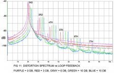
The measurement results are presented in fig 11 graph from the Pass Labs paper.
To verify this theory, Mr. Pass designed a Single Ended, MosFet amplifier,
connected to an 8 ohm load, biased at 2Adc, with an 11 Vdc across the gain device.
Mr Pass also used variable "degenerative" feedback - most probably a resistor inserted in the
Source circuit of the gain device.
Roughly, the ratio of this resistor to the output impedance defines the feedback loop gain of the gain block.
The measurement results are presented in fig 11 graph from the Pass Labs paper.
Attachments
I am unclear whether this is your statement or his. I am unclear whether you agree with it or state it in order to dispute it. However, it is false. Feedback applied in whatever way to any nonlinear circuit will give rise to some re-entrant higher order distortion. This distortion, like almost all distortion, will then be reduced by the feedback and in most cases will be too small to be of any significance especially when compared with higher order distortion already produced by the active devices.Alexiss said:Feedback, when localized, and specially in such simple and linear circuits used, should not give rise
to higher order harmonics components in an FFT graph, regardless of the amount applied.
Simulations I - continues
As clearly visible in fig 11 of Pass Labs document, the 15 dB feedback applied to the gain block, increases the amplitude of
ALL harmonics components above the 2nd.
Pass Labs claims "negative feedback can reduce the total quantity of distortion, but it adds new components on its own".
This simply appears not to be the case.
In order to find out more, a series of very simple simulations were performed.
A single ended, MosFet amplifier using IRFP240 transistor model, with a load of 8 ohms, biased at 2 Adc and Vds = 11 Vdc was used.
Running 1W into an 8 ohms load, two simulations were performed:
1- BLUE trace: no feedback applied
2- GREEN trace: 15 dB of negative, degenerative feedback applied.
Last edited:
Simulations I - results
As clearly depicted in the picture above, the application of 15 dB negative, degenerative
feedback, results in higher amplitude on virtually all harmonics components except for the 2nd.
This seems to agree with the proposition in the Pass Labs paper - that application of feedback
adds new components on its own.
Last edited:
Simulations I - results
As clearly depicted in the picture above, the application of 15 dB negative, degenerative
feedback, results in higher amplitude on virtually all harmonics components except for the 2nd.
This is well known and was described and reasoned in many papers, starting with Baxandall. The problem is too low feedback you use (15dB). Feedback makes sense and improvements when used in much higher amounts, like 60 - 100dB for the lower frequencies and at least 40dB at 20kHz (proper frequency compensation to be used). Please try to repeat your calculations with much higher feedback factor and you will see that the newly created frequency components will have negligible amplitude well below threshold of hearing. It is an utter nonsense to use only 15dB feedback.
Yes. As I think I said earlier in this thread: for feedback use none, or enough. A little feedback may be enough to create re-entrant distortion but not enough to suppress it. Small amounts of feedback should only be used in situations where distortion is already low so feedback is being used for some other purpose such as setting output impedance or widening bandwidth. Everywhere else, use none or lots.
Simulations II - thoughts
Since higher order harmonics are being created here obviously, it is highly unlikely that they are
due to application of feedback, specially degenerative feedback.
These higher-order harmonics are possibly due to a slight signal compression
somewhere in the output circuit loop.
A reduction in the Vds voltage due to the necessary insertion of the degenerative element in the output loop
might be the cause to this type of behavior.
Degeneratvie feedback, specially in such a worst-case-scenario, where the impedance of the degenerative
element is almost 20% of the output impedance, will effect the output voltage conditions quite substantially.
Applying feedback in general, specially 15dB of degenerative feedback, when the Vds loss (statically, but ideally even
dynamically) is compensated for will not lead to higher-order distortion or added complexity, it would be impossible.
But how can this be verified?
Last edited:
- Home
- Amplifiers
- Pass Labs
- Distortion and Negative Feedback