Zen Mod said:
yup ;
maybe ya all curlie wiggling habited boyz , but moi no ...... my curls are natural ..........

I feel like: "Welcome to the machine..."
Hold your horses!
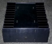
This is how I see it - There are just 10 -15 cases out there in the world that we were fortunate to get. The master worked on them, there are even hand written notes on fets with matching numbers. At least my intention is to keep it as much as possible as is. Nelson used these cases for his tests and experiments and in my mind it has a special value. My case is without power supply, and it has TO3 Mosfets installed. I would prefer to keep it as is, and the ideal case would be that someone has N channel only but would like to construct F4. That way we keep the cases intact we trade sides and we are all happy. I have no use for matched P channel mosfets, and someone will need just that. Instead of holding on it I sent it where it could have direct use, and preserve the original shape,
It is very easy for me to get TO247 package Mosfets and start drilling and tapping holes, but that is the last thing I would like to do on this case. You haven't seen the cases inside, majority of cases are with TO3 MOSFETS in the place with insulators and boards that are even with resistors in place. That is really worth preserving if possible and keeping as is. Out of that respect I offered in the first place to drill and tap a few needed holes for boards for everyone in this group, just to preserve these beauties as is.
Also on temperature specs I see this as a unique group effort, where everyone shares the same chasis, so from that perspective it applies to everyone and everyone has a interest of finding it out. What better place to start than asking the master itself who played with it, and knows how far it will go.
For everyone else on the list, my dear friend Choky is helping me with this project and he likes making fun of me. Sometimes well deserved on my side!

AR2 said:
.......
Hold your horses!
............

I just couldn't resist ........ teasin' ya all the time just to see few pics ......
(please ? slatko sa slagom ? cherry on top ? )

naah ... just wait ..... one day , when Papa adopt me , I'll have nicer box
jacco vermeulen said:cardboard
Attachments

Zen Mod said:
I just couldn't resist ........ teasin' ya all the time just to see few pics ......
(please ? slatko sa slagom ? cherry on top ? )
naah ... just wait ..... one day , when Papa adopt me , I'll have nicer box
I promise I will make few shots over the weekend.
Once I know what I'm doing with mine, AR2, maybe we can swap. I have one all-IRF240 amp and IRF244/IRF9240 pairs in the other. (I wrote earlier that these were IRF744 instead of IRF244 by mistake.)
There are schematics for most of the Alephs on http://www.kk-pcb.com/amps.html Too bad none of them have voltage rails based on 50-0-50 (or 25-0-25) trannies.
An Aleph 2 at higher rails with three pairs instead of six would work nicely for me: four channels, two for mids, two for tweeters in parallel. But only if the 240 can sub for the 244.
- Eric
1/2
for your future reference ........
feel free to put 240 or 244 ..........
Eric Weitzman said:Once I know what I'm doing with mine,............But only if the 240 can sub for the 244.
- Eric
for your future reference ........
feel free to put 240 or 244 ..........
Attachments
Some shots that have the amp chassis' in them. To give a preview.
http://www.diyaudio.com/forums/attachment.php?s=&postid=1639861&stamp=1224824347
http://www.diyaudio.com/forums/showthread.php?postid=1637142#post1637142
http://www.diyaudio.com/forums/attachment.php?s=&postid=1639861&stamp=1224824347
http://www.diyaudio.com/forums/showthread.php?postid=1637142#post1637142
Eric Weitzman said:Once I know what I'm doing with mine, AR2, maybe we can swap. I have one all-IRF240 amp and IRF244/IRF9240 pairs in the other. (I wrote earlier that these were IRF744 instead of IRF244 by mistake.)
There are schematics for most of the Alephs on http://www.kk-pcb.com/amps.html Too bad none of them have voltage rails based on 50-0-50 (or 25-0-25) trannies.
An Aleph 2 at higher rails with three pairs instead of six would work nicely for me: four channels, two for mids, two for tweeters in parallel. But only if the 240 can sub for the 244.
- Eric
Great Eric, that would work quite nicely for me. I am assuming that you have enclosure with 6 Mosfets pairs on one side (12 per side, 24 total). If you do than we could do complete side swap the size will match.
Regarding your plans, do you want to have two Aleph 2 channels in one enclosure or one? I am very positive that there is not enough cooling for two channels within one enclosure for that. And higher voltage with less mosfets on Aleph 2 will burn your mosfets.
What you should go for is Aleph 30 or Aleph 5. Aleph 5 uses 3 N channel pairs and your transformer voltage of 25v after rectification will give you around 34V what is exactly what Aleph 5 calls for. For that you need all N channel Mosfets. For any of them you can use 240 in the place of 244 and vice versa with no problems.
So if you decide to go different rout - F4 than I will be happy to exchange. In that case you will need complimentary pairs.
Nelson Pass said:Eric,
Given the hardware, I personally would build a stereo bass amp using the chassis with the complementary pairs, use the chassis with the
single-ended output stage for the midrange, and build a similar
smaller one for the top end.
Acctually this was the best advice, and explains everything. That way you do not have to change anything with your cases.
No disrespect to Nelson or AV2, but I don't need any more amps, let alone get these two gift amps running and then build a third amp from scratch.
A path is appearing in the fog: build two stereo A5 amps with 60 watts per channel and 1% THD.
Amp#1: Use every other 240 pair in one amp, that is, three pairs per channel, one channel on each side of the chassis. The transistors can be reconfigured by simply cutting traces and jumpering.
Amp#2: For the amp with the 244/9240 pairs, remove the 9240s and pair up the 244s. Or transplant the unused 240s from the first amp. All of which requires desoldering and unbolting transistors and remounting/resoldering.
An easier way is to put one case side+heatsink with the 240 pairs into each amp, but then both amp channels would share one heatsink while the other heatsink goes unused.
From a cursory scan of the Aleph M, it seems the driver boards from BrianGT would support both the A2 and A5 drivers.
I'd be happier with stereo A2s because the A2 has lower distortion (0.5% at 100 watts vs. 1% at 60 watts) but the transformer is wrong: 530VA vs. 600VA, 50-0-50 vs. 37-0-37. Thus my earlier question about running the A2 at higher voltage with fewer output devices. I don't understand why the mosfets would fry, AV2, because they can dissipate 125w, pass 18A, and have BVDSS of 200V, nothing near what 65V rails would subject them to. But I only understand the basics, so please enlighten me.
Nelson, the A2 and A5 drivers are very similar. Is the lower A2 distortion due to the cap changes in the second stage, or different mosfet bias, or something else entirely?
- Eric
If you lower amount of fets than you will increase the current that goes through each fet, since you are sharing the total current through each fet. That will automatically increase power dissipation that each fet does. If you increase voltage than that equation gets multiplied by that as well. If you ever owned any of Alephs, you would know that they act as a small space heather, that how hot they get. In my experience they are pushed to the max already, and there is no room for any further increase. Not unless you have huge heatsinks or forced cooling, or water cooling... These fets will burn not because they have low rating for voltage or current, but because of the heat.
I have Brian GT's mini Aleph boards and I run them in the exact configuration you are thinking about, Three pairs per channel, Aleph 30 configuration, with little bit higher voltage. I call them Aleph 305 since they are cross between the A30 and A5. They dissipate so much heat, it is hard to believe. With that in mind I could imagine what Aleph 2 does.
I am not sure about the distortion figures you are talking. More or less all Alephs are same, the main difference is that less fets you need in output better the top end. That is because mosfets do have relatively high internal capacitance, that act as a filter. More of paralleled fets, more capacitance, less high frequency goes out. That is one reason why many people like smaller Alephs, since they are ideal to run tweeters and mids. I am still to hear any amp that could compete with Alephs in that area.
I hope this helps.
Thank you, master. I now see that the current source mosfets dump their current into one node where the output mosfets pick it up and share it. I thought there was one current source for one output mosfet. So if fewer devices are used, or the voltage is raised, the current sources should be reconfigured so less current is available.
Maybe I will study more before asking any more questions.
I've never owned one, but had a friend's A30 here for a while. His transformer melted goo all over the insides. It might have been an A3. It was the one with the purple metal fur -- four sides of purple anodized heatsinks.
- Eric
Maybe I will study more before asking any more questions.
I've never owned one, but had a friend's A30 here for a while. His transformer melted goo all over the insides. It might have been an A3. It was the one with the purple metal fur -- four sides of purple anodized heatsinks.
- Eric
Eric Weitzman said:Thank you, master. - Eric
Ha, what do you say now Choky!
Thank you Eric, but I am definitely not worthy of the title you've given it to me. You are more than welcome to ask as many questions as you want. I see now you must be glad that you made the decision to visit Burning Amp in the end. Who would know after we spoke that night that you are going to end up with the first prize!
I am looking if you have all N channel MOSFETS IRFP044/240/244.
Would the IRFP140 (IR brand) strike your fancy? I'd have to look see if I have enough but I'd be up for a trade if I do.
Marc
Edit: yep, I've got a decent amount - let me know what you think would be fair if interested.
Edit Edit: Oh, as I read on I see you aren't looking for t0-247, which the IRFP140 is......
I'm confused by one thing in rev 0 of the Aleph 5 service manual (1996). The power consumption (150 watts per channel) jives with the statement that the three output CCS are set to 2A total (at +/-34V), but the voltage drop across each of the 1 ohm resistors is shown as 0.5V, implying that the CCS current is 1.5A instead. What am I missing?
BTW, AR2, I think adding or removing pairs *isn't* a problem (given enough drive) since one less (or more) CCS would feed one less (or more) output mosfet. I may have to reconsider calling you "master".
A new plan is shaping up: two three-channel Aleph 5 amp. Total power consumption per chassis will be 450VA, which is lower than the tranny rating. Two channels in each chassis would be two A5s using 240s (one "side" from the all-240 SE chassis) and the other channel would be one A5 using 244s using one side from the comp chassis with the mosfets reconfigured. There's a lot more power supply capacitance in the two-channel A5 than in my burningamps, so I'll have to deal with that. And add connectors, etc.
Some are skeptical that each Orion tweeter needs it's own 60 watt channel, but I have small amounts of some kinds of music that, when played at rock concert levels, have clipped other 60 watt amps. SL uses them down to 1.5hHz BTW. The power is not a need, but a desire!
- Eric
I think that will work fine, but probably the amp sinks will run pretty
hot, so do what you can to keep them ventilated.
As to the .5V callout on the schematic, that reflects the number I
pulled out of my butt while doing the schematic before it ever got
built. Our schematics are full of approximations like that.
hot, so do what you can to keep them ventilated.
As to the .5V callout on the schematic, that reflects the number I
pulled out of my butt while doing the schematic before it ever got
built. Our schematics are full of approximations like that.
Nelson Pass said:...........Our schematics are full of approximations like that.
Attachments

- Status
- This old topic is closed. If you want to reopen this topic, contact a moderator using the "Report Post" button.
- Home
- Amplifiers
- Pass Labs
- Burning Amps