Hi guys,
i am on the way of building the Aleph ONO.
These below are the modifications i am plannin on making to it:
1- PSU --> i will probably go for the shunty regulated PSU
2- Eliminate the 10uF output coupling cap by installing a variable resistor at the collector of Q1
3-Eliminate the inverter and use in case a specific output transformer to float the output (i will evaluate this in case)
4-Try to replace the led on the current source mirror's block with an appropriate voltage regulator to obtain maximum stability (i will run extensive listening tests and i will go for whatever solution sounds best)
5- I won't install jumpers for gain and cartridge regulation but i will "fit" the ONO to my specific needs by adjusting it to my pick up.
6- Try to see if i can, instead of using the the 220uF electrolytic coupling capacitor's type on the signal path, i will try to use a good 30uF polypropylene (i know that Nelson recently switched from a 10uF film cap at the output of the MC on the ONO to a 220uF on the Xono) because i think, beside film caps are bulky and pricey, they do sound better and cut frequency with a 30uF should still be enough low (around few Hz if i am not wrong), just my two cents.
if anybody wants to comment these 6 points is very welcome.
I have ordered the parts and they should get here pretty soon hopefully.
Tomorrow i will start working on the PCB design.
Today i have finished the simulation session so i have the complete model simulated on my laptop that is always helpful to debug an eventual circuit's fault.
I have few questions for you guys:
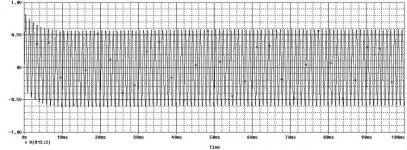
a) It seems on the simulation i have run, that there are 100ms settling time before the output waveform becomes symmetric (look at the picture attached).
Is this reasonable? I was thinking that it might be due to the RIAA equalization's network in the feedback path, may this be the reason?
I will use this stage along with my Denon DL 103 (0.35mV) but to do so i will need a gain around 70dB and i was wondering whether
b) it would be better to increase the gain of the MC stage or the MM stage (which is not very high anyways with its 40dB)?
therefore in case i would decide to increase the gain on the MC stage would it be better to:
b1) increase the current sense resistor R40 that apparently could be raise as much as i want, but what is the drawback of increasing this resistor?
b2)cascoding another 2sk170 in order to increase the current sourced to the emitter follower stage? but then wouldn't this increase the transconductance of the cascode increasing therefore distortion figure?
c)in case i would decide to increase the gain on the MM stage instead, where can i act? i was thinking of varying the values on the voltage divider on the feedback path R7/R21 but i am not sure.
Last thing:
from what i have learned so far here on this forum the more the devices are biased and the better they sound.
Therefore going of on this token i was thinking,
d)since the Push-Pull Class A output stage is biased at 10mA, has anybody tried to modify it by varying R56 and thus increasing the voltage drop at R38/27?
this operation would of course require heatsinks on the two devices but oh well.
Also is it not worth to increase a little bit the bias on the input differential stage of the dual nJFET 2SK389?
Or these bias points are what so called "sweet spot"?
Thank you guys very much for your attention.
Best,
i am on the way of building the Aleph ONO.
These below are the modifications i am plannin on making to it:
1- PSU --> i will probably go for the shunty regulated PSU
2- Eliminate the 10uF output coupling cap by installing a variable resistor at the collector of Q1
3-Eliminate the inverter and use in case a specific output transformer to float the output (i will evaluate this in case)
4-Try to replace the led on the current source mirror's block with an appropriate voltage regulator to obtain maximum stability (i will run extensive listening tests and i will go for whatever solution sounds best)
5- I won't install jumpers for gain and cartridge regulation but i will "fit" the ONO to my specific needs by adjusting it to my pick up.
6- Try to see if i can, instead of using the the 220uF electrolytic coupling capacitor's type on the signal path, i will try to use a good 30uF polypropylene (i know that Nelson recently switched from a 10uF film cap at the output of the MC on the ONO to a 220uF on the Xono) because i think, beside film caps are bulky and pricey, they do sound better and cut frequency with a 30uF should still be enough low (around few Hz if i am not wrong), just my two cents.
if anybody wants to comment these 6 points is very welcome.
I have ordered the parts and they should get here pretty soon hopefully.
Tomorrow i will start working on the PCB design.
Today i have finished the simulation session so i have the complete model simulated on my laptop that is always helpful to debug an eventual circuit's fault.
I have few questions for you guys:
a) It seems on the simulation i have run, that there are 100ms settling time before the output waveform becomes symmetric (look at the picture attached).
Is this reasonable? I was thinking that it might be due to the RIAA equalization's network in the feedback path, may this be the reason?
I will use this stage along with my Denon DL 103 (0.35mV) but to do so i will need a gain around 70dB and i was wondering whether
b) it would be better to increase the gain of the MC stage or the MM stage (which is not very high anyways with its 40dB)?
therefore in case i would decide to increase the gain on the MC stage would it be better to:
b1) increase the current sense resistor R40 that apparently could be raise as much as i want, but what is the drawback of increasing this resistor?
b2)cascoding another 2sk170 in order to increase the current sourced to the emitter follower stage? but then wouldn't this increase the transconductance of the cascode increasing therefore distortion figure?
c)in case i would decide to increase the gain on the MM stage instead, where can i act? i was thinking of varying the values on the voltage divider on the feedback path R7/R21 but i am not sure.
Last thing:
from what i have learned so far here on this forum the more the devices are biased and the better they sound.
Therefore going of on this token i was thinking,
d)since the Push-Pull Class A output stage is biased at 10mA, has anybody tried to modify it by varying R56 and thus increasing the voltage drop at R38/27?
this operation would of course require heatsinks on the two devices but oh well.
Also is it not worth to increase a little bit the bias on the input differential stage of the dual nJFET 2SK389?
Or these bias points are what so called "sweet spot"?
Thank you guys very much for your attention.
Best,
Attachments
I would think that the Ono is already a pretty perfect design and cannot easily be improved. But since I cannot help tinkering and am (still) in the process of building my own version – or corruption - of the Ono, here are some ideas or comments that I have:
@ 1 : Don’t know this particular reg. but shunt reg’s are said to be good sounding and are certainly a good idea. Additionally, you could try cap. multipliers for the MM stage instead of the 1000uF caps C12 / C20. For the MC stage, I saw an alternative cap. multiplier approach in John Curl's Vendetta MC stage that might be worth a try. He is using JFets and the biasing is set via an additional selected JFET current source / resistor. You could leave the BJT for Q24 but still use a current source / resistor to set the bias, but this is creating a voltage "reference" and you need to select the current and resistor value.
@ 2 : One alternative would be a “variable resistor” in the current source allowing to adjust the bias ever so slightly.
@ 3 : Do you really need the balanced out, maybe a single ended output would be sufficient ?
@ 4 : I would think that the LED is pretty stable and low noise already. You could possibly add an RC filter to Q16. Secondly, you could cascode the current source(s) Q16 (and Q17). A BF245C or similar JFET with high pinch-off voltage might be sufficient. For thermal stability - when eliminating the output cap. – you could replace Q16&Q17 with a dual matched NPN transistor such as SSM2210 (does not cost too much), or 2SC3381 if you can still get them (I learnt they were actually conceived as cascode devices for the 2SK389?)
@ 5 My plan too, If gain setting is not required you could throw out R66, R81, and combine R41 and R80 into one single resistor. Btw., I read somewhere that C16 has been omitted in the XONO.
@ 6 : Personally I would leave the electrolytic caps.
MRupp,
i can finally give you a detailed answer.
with regard to the balance output: no i don't really need it now since i don't want to go through the hassle of stray noise pick up by the cartridge due to the fact that one of the cold signal is not common grounded (if i want a real balance line from the wiring of the tonearm).
Led are stable and low noise, but of course not a much as this baby here :
:
MAX6265
I got the idea of using the 2SC3381 last night as i was searching for a low noise NPN device.
As for the availability a quickie google shows different options at different price mand you can find it for cheap.
The only problem is if it the part is genuine or not.
You gave me a good hint with the cascode.
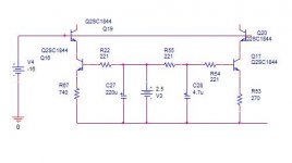
I therefore have fold cascoded the 2 transistors (as shown on the pic) although I don't think there will a great benefits by doing so since the cascoding helps lowering the input capacitance and thus increasing the linearity/stability ah high frequencies allowing the block to be driven by an higher load.
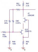
Speaking of cascode though, i have thought of cascoding the voltage gain stage of the MC section Q15 by using an high pinch-off N-JFET such as 2SK246 which should shunt the input capacitance down to 50pF: good enough!
(picture attached on the next post)
In order to achieve a gain of 70dB, i figured that it wouldn't be so smart to increase the current sense resistor R40 because this might cause a roll off of the high frequencies due to a lower cur frequency (even though with the cascoding should help quite of a bit here).
Instead what i have thought it would have been preferable here is:
a) parallel more transconductance matched n-jfet since the 2SC1844 can manage up to 100mA.
this would enhance the noise figure but with the drawback of more transconductance and supposedly more distortion at highs.
Since i don't have 2SK170GR but only BL types i can't follow this path.
This is my idea of how to increase the gain:
if i keep the 4 paralleled devices and use the BL type and leave the 22ohm source resistor i have a total of 26mA and each jfet is biased at 6mA which is the supposedly good spot (linear region) and use 470ohm as current sense resistor i achieve 70dB of total gain.
I think that keep the current sense resistor low is good and also bias the jfet up to their linear area beneficial.
that's it, any comment is welcome.
i can finally give you a detailed answer.
with regard to the balance output: no i don't really need it now since i don't want to go through the hassle of stray noise pick up by the cartridge due to the fact that one of the cold signal is not common grounded (if i want a real balance line from the wiring of the tonearm).
Led are stable and low noise, but of course not a much as this baby here
:MAX6265
I got the idea of using the 2SC3381 last night as i was searching for a low noise NPN device.
As for the availability a quickie google shows different options at different price mand you can find it for cheap.
The only problem is if it the part is genuine or not.
You gave me a good hint with the cascode.
I therefore have fold cascoded the 2 transistors (as shown on the pic) although I don't think there will a great benefits by doing so since the cascoding helps lowering the input capacitance and thus increasing the linearity/stability ah high frequencies allowing the block to be driven by an higher load.
Speaking of cascode though, i have thought of cascoding the voltage gain stage of the MC section Q15 by using an high pinch-off N-JFET such as 2SK246 which should shunt the input capacitance down to 50pF: good enough!
(picture attached on the next post)
In order to achieve a gain of 70dB, i figured that it wouldn't be so smart to increase the current sense resistor R40 because this might cause a roll off of the high frequencies due to a lower cur frequency (even though with the cascoding should help quite of a bit here).
Instead what i have thought it would have been preferable here is:
a) parallel more transconductance matched n-jfet since the 2SC1844 can manage up to 100mA.
this would enhance the noise figure but with the drawback of more transconductance and supposedly more distortion at highs.
Since i don't have 2SK170GR but only BL types i can't follow this path.
This is my idea of how to increase the gain:
if i keep the 4 paralleled devices and use the BL type and leave the 22ohm source resistor i have a total of 26mA and each jfet is biased at 6mA which is the supposedly good spot (linear region) and use 470ohm as current sense resistor i achieve 70dB of total gain.
I think that keep the current sense resistor low is good and also bias the jfet up to their linear area beneficial.
that's it, any comment is welcome.
Attachments
the more i look at the folded current mirror and less sense this makes sense to me.
Do you guys think that this configuration might have any kind of advantages over the normal current mirror?
Since i don't have the output coupling cap anymore i was wondering if i still really need the R14/15/28/30 , C8 anymore?
I can't understand why this parts are there (i think that was to obtain a low cut off freq with the 10uF but not sure)
Sorry, don’t have much time now, so quickly, and I can only give you my own personal opinion - though I have not personally tried or compared most of the options (yet):
I do not understand what the balanced output has to do with balanced input, are you not confusing the two? The Ono is a single ended phone stage that only creates a balanced output signal to connect to a balanced preamp.
I know Borbely is using this approachand and you can off course do this but I do NOT like the idea at all. From all I have learned so far the K170 is more linear at higher Vds of say 8 – 10 Volts minimum. Actually I read a WEB article where someone varied Vds in a similar setup and heard clear sonic degradation at 6 volts or lower; he stayed well above this threshold to be on the safe side.
The Ono is using a 1K option for increased gain and I should be very surprised if this is a liability. Why do you not just raise the voltage to accomodate the voltage drop across a 1K drain resistor, possibly lower Vds to 10 Volts also.
with regard to the balance output: ...
I do not understand what the balanced output has to do with balanced input, are you not confusing the two? The Ono is a single ended phone stage that only creates a balanced output signal to connect to a balanced preamp.
Can’t find this particular part but it can’t do any harm if it is a good voltage reference.MAX6265 ...
The reason for the cascode is that simple current sources have a much lower impedance and lower bandwidth compared to a cascoded CS, see also the recent articles from Walt Jung on current sources. Not sure if this is audible but I do have BF245C (to be found on ebay relatively cheap) and a cascode is straightforward.I therefore have fold cascoded the 2 transistors ...
Speaking of cascode though, i have thought of cascoding the voltage gain stage of the MC section Q15 by using an high pinch-off N-JFET such as 2SK246 ...
I know Borbely is using this approachand and you can off course do this but I do NOT like the idea at all. From all I have learned so far the K170 is more linear at higher Vds of say 8 – 10 Volts minimum. Actually I read a WEB article where someone varied Vds in a similar setup and heard clear sonic degradation at 6 volts or lower; he stayed well above this threshold to be on the safe side.
In order to achieve a gain of 70dB, i figured that it wouldn't be so smart to increase the current sense resistor R40 because this might cause a roll off of the high frequencies ...
The Ono is using a 1K option for increased gain and I should be very surprised if this is a liability. Why do you not just raise the voltage to accomodate the voltage drop across a 1K drain resistor, possibly lower Vds to 10 Volts also.
HI MRupp.
sorry i didn't explain myself very well.
Of course this is a single end stage.
I was thinking one thing and wrote another ...
you can find it on digikey
http://search.digikey.com/scripts/DkSearch/dksus.dll
type
MAX6225AEPA+-ND
It an high end voltage regulator.
Thanks, you have just answered to my previous question where i was wondering what advantages there are by having such a folded cascode current mirror.
I have cascoded it with the 2SC3321.
Do you think it is better to use the BF345 you mentioned?
yeah i am not sure that an higher current sense resistor would be worse now that i am thinking through actually a 1K won't change that much the input impedance of the gain stage over a 470 since there is a 4K in series the coupling cap.
Anyways it appears better to me to increase the current of the jfets: by doing SO you will push the jfets on the more linear region.
What you've brought up with regard to the 6V VDS is really interesting.
On my set up VDS of Q15 is only 500mV.
I might decide to drop this solution eventually.
i would also like a comment on this, if possible, from Nelson Pass or other members too.
i will make researches on this.
.... I have cascoded it with the 2SC3321. Do you think it is better to use the BF345 you mentioned?
There are many ways of implementing current sources, I just have these transistors and it is an easy way of cascoding though it might not be better in any other aspect ... Go read the Jung articles!
yeah i am not sure that an higher current sense resistor would be worse now that i am thinking through actually a 1K won't change that much the input impedance of the gain stage over a 470 since there is a 4K in series the coupling cap.
I do not understand what that has got to do with the input impedance, are you sure you are not confusing something ?
Please correct me if i am wrong:
the input impedance seen by Q15 is also determined by R40 (try to draw a small signal model of the system).
If this is so, what i was thinking was (I don't know if this is correct though):
the voltage gain stage Q15 has a certain Cin (lowered by cascoding with that n-jfet) : wouldn't this Cin combined with Rin of the stage determine the input cut off frequency of the stage?
If this is reasonable,actually, the result would be that: the higher R40 and the lower the cut off frequency thus causing a roll off on highs.
I am sure i am missing something because I am sure that C19 should also be taken in consideration for the cut off freq i guess an C19 is a 220uF.
Please, if i got the wrong view point, i would appreciate if you can correct it.
As for the article, i will definitely go and read it.
Thanks for the hint you gave me and the good advice.
I appreciated it.
Best,
P.S. did you find the voltage regulator on digikey? what do you think?
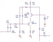
voltage gain stage Q15
OK, now I get it, did not realise that you were cascoding the second stage. First of all, I still do not like this type of cascode for JFETs.
Secondly, this is already a unity gain stage or "drain follower" (amplification -1) by means of feedback, so I am not sure from the top of my head how you calculate the input capacitance but my first guess is that it is already in the same ballpark as that of a cascode. Btw. I would make R41 and R51 about the same if you omit the gain setting resistors.
Hi,
first of all, I did not build the ono but experimented a bit with 2SK170 in the front end of an MC-headamp.
If you already simulate the ono, you should easily see differences when trying out cascoded jfet's and, hence, different Vds-values. It seems that indeed something between 8-12Vds might be the optimum value.
I have abandoned cascoding the input jfet for a MC-headamp:
1) the cart's signal voltage is so small, so the corresponding variyng drain voltage shouldn't introduce too much distortion, 2) MC-carts are not sensible to that dimensions of input capacitance.
You need to handselect the 2sk246 for Vgs if you want them as cascodes, you might find that you won't find some that fit in well - and definitly none above 8V ;-)
Remember, I'm only talking 'bout the input stage!
Rüdiger
MRupp said:
OK, now I get it, did not realise that you were cascoding the second stage. First of all, I still do not like this type of cascode for JFETs.
Secondly, this is already a unity gain stage or "drain follower" (amplification -1) by means of feedback, so I am not sure from the top of my head how you calculate the input capacitance but my first guess is that it is already in the same ballpark as that of a cascode. Btw. I would make R41 and R51 about the same if you omit the gain setting resistors.
thank you MRupp for your answer.
i don't get it: why would you wanna make R41 and R51 the same value?
Sencond, i don't get it: how is Q15's atge on the MC a drain follower by means of feedback? I mean the stage is a common source with 4.75K feedback resistor and 220uF cap that only blocks the feedback path at frequencies around DC.
thank you very much for your attention.
Onvinyl said:Hi,
first of all, I did not build the ono but experimented a bit with 2SK170 in the front end of an MC-headamp.
If you already simulate the ono, you should easily see differences when trying out cascoded jfet's and, hence, different Vds-values. It seems that indeed something between 8-12Vds might be the optimum value.
I have abandoned cascoding the input jfet for a MC-headamp:
1) the cart's signal voltage is so small, so the corresponding variyng drain voltage shouldn't introduce too much distortion, 2) MC-carts are not sensible to that dimensions of input capacitance.
You need to handselect the 2sk246 for Vgs if you want them as cascodes, you might find that you won't find some that fit in well - and definitly none above 8V ;-)
Remember, I'm only talking 'bout the input stage!
Rüdiger
thank you for your post.
gotcha!
A good casconding sets the VGS of the cascoded stage to about 7V or so.
I will try to see if i can cascode by tapping the voltage reference at the gate of the cascode Jfet as a voltage divider and see if i can set VDS of Q15 higher.
I will have to try tomorrow.
But thank you all for your useful posts.
I have pulled out the juang's article on current source and the long article on hi end regulator and started to look at them.
I will take anyways a couple of days to read and start digesting them.
Just a curiousity: has anybody ever tried to implement the juang's super regulator and thus can report the sound of such a supply.
I will eventually evaluate to use it over the shunty, not sure yet.
With regard to the cascode of Q15 and your advice of having a VDS over 6V, this is the modification of the cascoding.
The Drain of Q15 is held at 8.25V and the source at 0.2V so VDS is 8V.
Is this cascoding properly done now?
Attachments
Hi Stefano,
what is the purpose of R51/C19?
There were debates wheter a fet or a bjt as cascode device would sound better. NP once said, bjt, and Borbely votes for fet's. Maybe you can try both and report back?
Personally I think the jung regulator can make a good circuit sound even better. In fact, I liked it whereever I tried it. But, it would make a different concept and additional changes *might* be on their way. For instance, is the cap multiplier ahead of the input stage still needed then?
If I were to mod the ono, I would build the original circuit and try my modifications from there. (eventually planning the circuit board in way that would allow those mods)
Rüdiger
Onvinyl said:I have abandoned cascoding the input jfet for a MC-headamp:
1) the cart's signal voltage is so small, so the corresponding variyng drain voltage shouldn't introduce too much distortion, 2) MC-carts are not sensible to that dimensions of input capacitance.
3) Sounds better without cascoding, at least to my ears.
4) Loses a coupling cap in a very sensitive place.
A common cathode FET (paralleled if required), powered by either Jung reg or batteries is very close to the ultimate SS MC stage soundwise. And there is no need for a monstrous coupling cap.
Onvinyl said:Hi Stefano,
what is the purpose of R51/C19?
There were debates wheter a fet or a bjt as cascode device would sound better. NP once said, bjt, and Borbely votes for fet's. Maybe you can try both and report back?
Personally I think the jung regulator can make a good circuit sound even better. In fact, I liked it whereever I tried it. But, it would make a different concept and additional changes *might* be on their way. For instance, is the cap multiplier ahead of the input stage still needed then?
If I were to mod the ono, I would build the original circuit and try my modifications from there. (eventually planning the circuit board in way that would allow those mods)
Rüdiger
Hi Rudiger,
thank you very much for your post.
I will definitely try them both, i mean BJT and FET as a cascode and report back what sounds the best.
About Jusng super regulator it sounds interesting.
You have successful tried it hum? interesting!
I possibiliy use this concept for the regulator on the current mirror in place of the led or the MAX IC.
My plan is to get the original circuit right on a protoboard and from there go off and try once upon a time all the modifications.
I am very sorry, i haven't understood what you tried to say here:
"But, it would make a different concept and additional changes *might* be on their way. For instance, is the cap multiplier ahead of the input stage still needed then?"
One more observation:
I have run simulations for different values of the coupling caps on the MC stage, trying to substitute the 220uF caps with a 10uF first and a 30uF then.
I am not going to post this bulky posts here of course
but i can report that there is a noticeable difference on the bottom end response by decreasing the values.Therefore i guess i will go for the 220uF.
The point is that i don't like to have electrolytic caps on the signal path even though i would use a good rubycon (as far as i have read are far better than the blackgate
 ).
).One more thing: speaking of frequency response: the simulation doesn't show a very wide band as in fact the top cut frequency is set to around 40KHz and the RIAA tolerance is 0.1dB within 20 and 20KHz.
I was wondering if the top cut freq as well as the tolerance (this of course) could be determined by the choice of proper values on the RIAA stage and if this and anyone has ever tried to redo it with a certain degree of improvement.
I have found a post on xonobal by Cheff where he designed a balance prototype of the xono with a riaa response of 0.03dB that is not pretty bad.
I would like to see if it is possible to improve the RIAA accordingly.
- Status
- This old topic is closed. If you want to reopen this topic, contact a moderator using the "Report Post" button.
- Home
- Amplifiers
- Pass Labs
- a couple of questions on the phono ONO