Charles Hansen said:Anyone wanting to build one of these should do so soon. The 2SJ74 was discontinued at the start of the year. Some of the distributors will have them in stock for another year or so, but after that they will become very difficult to find.
I recall you posting that you bought about a million of them. What is your phone
number again?

Fuling said:I recognize the circuit, Circlomanen made something VERY similar a couple of years ago
I recall that Circlomanen had a strong interest, but I can't find the schematic. Can you
post it or point us to it?
> I recall that Circlomanen had a strong interest, but I can't find the schematic. Can you post it or point us to it?
Pleasure.
http://www.diyaudio.com/forums/showthread.php?s=&threadid=55361
And this one from me has been built with various MOSFET types & configurations. Sounds very nice and absolutely DC stable.
http://www.diyaudio.com/forums/showthread.php?postid=931056#post931056
Patrick
Pleasure.
http://www.diyaudio.com/forums/showthread.php?s=&threadid=55361
And this one from me has been built with various MOSFET types & configurations. Sounds very nice and absolutely DC stable.
http://www.diyaudio.com/forums/showthread.php?postid=931056#post931056
Patrick
I recall that Circlomanen had a strong interest, but I can't find the schematic. Can you post it or point us to it?
Edit: Sorry, didn´t see that EUVL had already linked to the schematic.
Attachments
They are similar to be sure. Circlomanen is very prolific, and my hat is off to him. His name says it all.
I can promise you though, I worked this one out independently, as evidenced by my large collection of failed prototypes, and fets that made the ultimate sacrifice. The F5 provided the "lightbulb over the head."
Should there be a famine of Toshibas, if you check my blog you'll find a picture of the "Antimatter" LSK version of the boards, which will be tested right after RMAF.
mrothacher said:"Antimatter" LSK version of the boards, which will be tested right after RMAF. [/B]
I haven't looked for those posts yet, but would I be right in assuming that you're flipping Ps and Ns to use LSK389s for the input and something like FQA12P20s for the output? That would seem to make sense to me: Not only using a dual JFET that is (I believe) still in production, but also one that allows for significantly higher rail voltages....
> I can promise you though, I worked this one out independently,
I am sure you did, and it was a very good write-up in any case.
Thank you for raising the interest in Circlotron circuits again.
I remember when I saw the first circuit from Circlomanen, I discarded it as eccentric.
Ever since I built my first a year ago, I have not been building anything else.
I think people discard the topology without understanding its many virtues.
Patrick
MEH said:
I haven't looked for those posts yet, but would I be right in assuming that you're flipping Ps and Ns to use LSK389s for the input and something like FQA12P20s for the output? That would seem to make sense to me: Not only using a dual JFET that is (I believe) still in production, but also one that allows for significantly higher rail voltages....
See my blog here: www.audiohobby.com
EUVL said:Thank you for raising the interest in Circlotron circuits again.
Bitte schön. My Pleasure.
Could somebody who understands both the F5 and The Amazing FET Circlotron better than I do please write a brief compare and contrast between the feedback mechanisms in these two circuits? With the all-but-perfect matching of input JFETs and output MOSFETs in the circlotron, it seems that the circlotron should have the potential to produce even better measurements than the F5; but it's not really all that close -- with the F5 ahead pretty much across the board in terms of distortion, slew rate, frequency response, etc. Is this just because of a lack of open loop gain and feedback in the circlotron?
Magura said:So now all that's left to do, is to make an inductor loaded version
Magura
Circlotron that will be ....... hardly
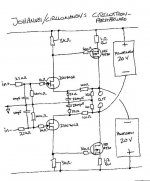
nearest variant , with choke implemented , was called PPP - PushPullParallel ... in tube world ; (NB - that's not Parallel Push Pull)
load is attached to autoformer , connected between cathodes of two output halves
edit:
http://www.jogis-roehrenbude.de/Verstaerker/PPP-EL84.htm
Attachments

Yes, my best guess is that the lower open loop gain, and therefore lower NFB, accounts for most of the difference. There are, no doubt, other contributing factors such as slightly higher noise and so on.
As I recall the output impedance is around .3 Ohms @ 1K also due to lower NFB, and this is another area where the F5 does better.
I had originally anticipated a small improvement in THD due to better symmetry, forgetting the output stage doesn't contribute voltage gain. Still, I'm pleased with the outcome.

Magura said:So now all that's left to do, is to make an inductor loaded version
As I mentioned, Circlomanen is very prolific. And, he winds his own coils
Look here
tubecad.com has quite a few very good articles on circlotron, including :
http://www.tubecad.com/2008/03/blog0137.htm
Patrick
http://www.tubecad.com/2008/03/blog0137.htm
Patrick
As I mentioned, Circlomanen is very prolific. And, he winds his own coils
Thank you very much for the kind words.
Funny thing that you came up with the same typ of circuit.
The do sound wonderfull!!
Johannes.
So now all that's left to do, is to make an inductor loaded version
I dont see any reason to build a two-stage amp with inductor-loading.
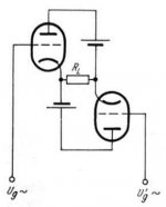
My Zenitron-amp works nice. It is a one-stage design, with a big inductor.
Its just a bit unstable with bad powersupplies.
Like with any really simple amp, the supplies needs to be really stable and quit.
Johannes.
An externally hosted image should be here but it was not working when we last tested it.
This is the basic circuit for the zenitron.
- Home
- Amplifiers
- Pass Labs
- The Amazing Fet Circlotron by Mike Rothacher