I am afraid that you do not understand the "triode" mode in LU1014 fully and how the DAO circuit really functions.
Both the effective resistance of the cascode device (1/Yfs for FETs or Re for BJT) and the degeneration resistor contributes to a dynamic change in Vds that just counteracts the quadratic behaviour of the Id vs Vgs, resulting in the published linear behaviour around bias.
http://www.diyaudio.com/forums/pass...urce-follower-configurations.html#post1595867
The values in my published circuit were not there by chance. They were results of 20 hours of experimentation. It may look very simple in the end, but it is not.
Maybe you should try the original circuit one day.
Cheers,
Patrick
T
Last edited:
Let me add that the effective resistance of the cascoding MOSFET or BJT is not entirely linear. However, they are non-linear in a different manner; MOSFETs are close to low-order polynomials, BJTs to exponential functions. In general BJT has a lower Re at the same bias, so you can use a BJT at the cascode position and try to get back some of the dynamic Vds change by increasing the degeneration resistor. But then you are trying to replace a quadratic device by an exponetial device + a linear device. It will never be 1:1 replacement. And in doing so, you have increased the output impedance (by about 2 ohms).
Maybe it is better, maybe it is not. I have not tried, so I simply don't know.
And you would notice the difference more if you are using the follower to drive a low impedance (hence high current) phone, like Grado's or AKG's.
The jury is still out, as far as I am concerned.
Patrick
Maybe it is better, maybe it is not. I have not tried, so I simply don't know.
And you would notice the difference more if you are using the follower to drive a low impedance (hence high current) phone, like Grado's or AKG's.
The jury is still out, as far as I am concerned.
Patrick
Last edited:
It seems to me that you missinterpreted the way your circuit works. There is no "dynamic Vds change". Vds stays constant regardless of signal, Yfs or Id change... There are microscopic changes due to inherent non-linearities of component itself but they are so tiny that they can be safely disregarded.
No need to spread mysticism about this circuit - it's a great headamp even without it")
No need to spread mysticism about this circuit - it's a great headamp even without it
> Vds stays constant regardless of signal
You cannot be more wrong. I designed it; I measured it; I know. Vds only "stays constant" if there is no load (RL >>300R).
And there is no need to accuse me of spreading mysticism even if you could not get what I was trying to tell you.
If you would bother, go and read Nelson's article on ZenV9 again please, the part on cascode modulation (what I called dynamic Vds).
Compare his Fig.2 & Fig.4, and the schematics of the DAO, to be precise. And check the Yfs of the cascode MOSFET at 200mA.
Patrick
Last edited:
Temper, temper, kuhl bleiben bitte
ZV9 has nothing in common with DAO except the parts used - that cascode is completely different pair of trousers. In ZV9 elko at cascode MOSFET's gate is grounded - in DAO it enbles MOSFET's Source (JFET's Drain) to exactly follow the JFET's Source.
Anyway, there is no need for me to prolong this discussion, you can't make me believe in magic.
Again, lovely circuit
Last edited:
I hate to do this, but I am doing this for the other guys, not you.
As in ZV9, the DAO circuit I published has a cascode MOSFET, the gate of which is tied to a voltage reference (in case of the DAO the Zener diode and a cap in parallel). The other end of the Zener diode is tied not to the source of the LU1014, but to the lower end of the source resistor (ca. 3 ohm in the DAO). Thus,
Vds of LU1014 = V zener - Vgs(cascode) - I x Rsource ................(Ohm's Law)
Suppose you have a load of 20R (Grado), and you apply a signal of 1V pk-pk (sine). This means output power
p = V^2 / (2 * R phone) = 25mW so not excessive.
The peak output current i = 1V / 20 ohm = 50mA.
Thus the voltage drop at the source resistor (3R) will increase by 50mA * 3R = 0.15V.
The Vgs of the cascode MOSFET will also increase due to the increase in current, by an amount of
vgs cascode = 1/Yfs * 50mA = 80mV.
Thus, vds of LU1014 will decrease by 230mV. This vds drop is output current (hence signal) dependent.
It is precisely this decrease of vgs that causes the triode effect (the linear portion of the curve I published in post #26).
Of course this is not the whole story, as we have only been discussing quasi-static effects so far.
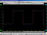
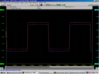
If you use the DAO with a 200R load (e.g. Sennheisser), you will see some overshoot when applying a 10kHz square wave. Where as if you reduce the load to 66R (e.g. AKG), the square wave is just about perfect. So it is not for no reason I keep saying that the published DAO is optimised for the AK701 / 702.
Which one sounds better ? That depends on the headphone (how much HF roll off it has). Can this dynamic behaviour be changed ? You bet.
A simple, naive looking circuit is much more complicated to design that it looks on the surface.
But no magic, just science intelligently applied.
Good day,
Patrick
(Magenta is input, red is output. Left is RL 200R, right is RL 66R.)
As in ZV9, the DAO circuit I published has a cascode MOSFET, the gate of which is tied to a voltage reference (in case of the DAO the Zener diode and a cap in parallel). The other end of the Zener diode is tied not to the source of the LU1014, but to the lower end of the source resistor (ca. 3 ohm in the DAO). Thus,
Vds of LU1014 = V zener - Vgs(cascode) - I x Rsource ................(Ohm's Law)
Suppose you have a load of 20R (Grado), and you apply a signal of 1V pk-pk (sine). This means output power
p = V^2 / (2 * R phone) = 25mW so not excessive.
The peak output current i = 1V / 20 ohm = 50mA.
Thus the voltage drop at the source resistor (3R) will increase by 50mA * 3R = 0.15V.
The Vgs of the cascode MOSFET will also increase due to the increase in current, by an amount of
vgs cascode = 1/Yfs * 50mA = 80mV.
Thus, vds of LU1014 will decrease by 230mV. This vds drop is output current (hence signal) dependent.
It is precisely this decrease of vgs that causes the triode effect (the linear portion of the curve I published in post #26).
Of course this is not the whole story, as we have only been discussing quasi-static effects so far.
If you use the DAO with a 200R load (e.g. Sennheisser), you will see some overshoot when applying a 10kHz square wave. Where as if you reduce the load to 66R (e.g. AKG), the square wave is just about perfect. So it is not for no reason I keep saying that the published DAO is optimised for the AK701 / 702.
Which one sounds better ? That depends on the headphone (how much HF roll off it has). Can this dynamic behaviour be changed ? You bet.
A simple, naive looking circuit is much more complicated to design that it looks on the surface.
But no magic, just science intelligently applied.
Good day,
Patrick
(Magenta is input, red is output. Left is RL 200R, right is RL 66R.)
Attachments
Last edited:
Hi Patrick
Thanks for the food for thought!
Just to make sure we're all on the same page, I've attached a circuit (copied from one of your earlier attachments).
As I understand it, the linearization mechanism you described above would apply even for a fairly simple follower e.g. just the Q1+Q11 part of the circuit, with a simple current source at the bottom.
Looking at the bigger picture, I see the same arguments applying to the linearity of the active source made of Q2+Q22.
One question, though - Doesn't Q3's non-linearity throw a spanner in the works, or is it relatively insignificant?
(Sorry if it's a dumb question, but I'm a total noob regarding fets)
Regards - Godfrey
Thanks for the food for thought!
Just to make sure we're all on the same page, I've attached a circuit (copied from one of your earlier attachments).
As I understand it, the linearization mechanism you described above would apply even for a fairly simple follower e.g. just the Q1+Q11 part of the circuit, with a simple current source at the bottom.
Looking at the bigger picture, I see the same arguments applying to the linearity of the active source made of Q2+Q22.
One question, though - Doesn't Q3's non-linearity throw a spanner in the works, or is it relatively insignificant?
(Sorry if it's a dumb question, but I'm a total noob regarding fets
)Regards - Godfrey
Attachments
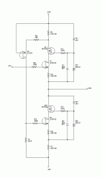
> Just to make sure we're all on the same page, I've attached a circuit (copied from one of your earlier attachments).
You posted the one with the Taylor current source.
I was talking about the original circuit posted in Grey Rollins thread.
> As I understand it, the linearization mechanism you described above would apply even for a fairly simple follower e.g. just the Q1+Q11 part of the circuit, with a simple current source at the bottom.
Yes.
> Looking at the bigger picture, I see the same arguments applying to the linearity of the active source made of Q2+Q22.
In the TCS circuit, yes. Absolutely.
> One question, though - Doesn't Q3's non-linearity throw a spanner in the works, or is it relatively insignificant?
Very good question. It does.
So in theory it is better to use a high gain device there, such as 2SA970, as in the original circuit of the TCS in tubecad.com.
This would minimise the effect of Q3.
However, I had the 2SJ103 lying around, and I actually tried it. I ended up getting a good working point, where I traded a bit of 2nd harmonics for reduced high order (3rd, 4th, 5th, ...). So I did not bother to try PNP afterwards. And I would suspect that a PNP will get me more high order harmonics.
But feel free to experiment and report back.
Regards,
Patrick
Last edited:
Hi Guys,
My plans are taking shape; I'm going to use heatsinks from an old Le Monstre build that I never listen to. That ran +/-14V rails at 0.5A bias and they didn't get too hot (about 57 degrees C, if I recall correctly) so they should be adequate to handle this, as long as I use rail voltages around between +/- 16 and +/- 20V or so, and bias around 200mA. PSU will be in a separate case, EI trafo, circuit to be defined later.
I have a few specific questions.
1. The schematic I am following is the one Godfrey posted above, which shows R2 at 4.7R and R3 at 5.6R, whereas the board Patrick posted in #47 has them at the same value. Did I miss something in the discussion above? Am I using the latest version of the schematic?
2. If I lower rail voltages to +/-16V or so (higher would be OK if the heatsinks can take it), should any of the component values be altered?
My guess is no, as long as I don't mind the bias current dropping, but I presume I could also raise that again by lowering R11 and R21?
3. I can't seem to get my hands on 2SJ103. I have 2N5460 on hand, and getting 2SA970 (which were mentioned just above) should be no problem, so I could substitute one of these for Q3. What changes in component values would be needed, and which would be a better option? (I can see about getting other substitutes also, if anyone has a better suggestion.)
4. Up above, Patrick suggested using a jfet with gate and source tied together in place of J511. This seems pretty straightforward, but does it make no difference whether it's a N- or P-jfet? I presume N- would go in the other way round from P-?
Thanks for any help.
Cheers
Nigel
Last edited:
1. I do not consider 3x12R // to be same as 3x15R //, but use the values in post #128.
2. No, and bias will not change practically, but you lose head room. So no 200R phones.
3. If you want to use 2SA970, you will need to change all values around the Taylor Current Source. See Tudecad.com for details (if you know what you are doing). Otherwise I suggest you build the simple DAO first and mod to TCS later when you can get the 2SJ103. Or ask Steenoe if he has some left.
4. N is easier to get than P and has less capacitance. You can also use a resistor that will give you about 4mA to the Zener.
Patrick
Hi Patrick, thanks for the replies.
I think you're right - better to do the DAO without Taylor first and then add it later. Should be interesting to compare "before" and "after", quite apart from the problem of finding the jfet. I've posted a copy of a schematic I pulled from a post of Steenoe's in the other thread. Is this the latest version without Taylor?
Neither do I, but the board doesn't appear to show that - the source resistors are 3x12R //, but R2 and R3 seem to both be 2x15R // 1x12R, as per the post just above, #46. That's OK, though, you answered my question just fine. If I do the DAO without Taylor first, then, I presume I leave out R2 and R3 (and jumper them on the board). But why have R11 and R21 been changed from 3R (in the old thread) to 3.9R here? Is it part of the Taylor mod, or just to change bias or something?
No problem; I plan to buy AKG701 or 702 to use with this. I'll try rails at +/- 16 or +/- 18V or so and see what happens.
Well, as you may have spotted (!!) I only partially know what I'm doing so maybe using 2SA970 isn't the best idea...
I'll build the DAO first and then see....
Fine - I've get several 2N5457 here somewhere, so I'll look for ones with Idss around 4mA (Right?) Is there any advantage to trying to match them for Idss at top and bottom?
Thanks again for the help
Cheers
Nigel
I think you're right - better to do the DAO without Taylor first and then add it later. Should be interesting to compare "before" and "after", quite apart from the problem of finding the jfet. I've posted a copy of a schematic I pulled from a post of Steenoe's in the other thread. Is this the latest version without Taylor?
1. I do not consider 3x12R // to be same as 3x15R //, but use the values in post #128.
Neither do I, but the board doesn't appear to show that - the source resistors are 3x12R //, but R2 and R3 seem to both be 2x15R // 1x12R, as per the post just above, #46. That's OK, though, you answered my question just fine. If I do the DAO without Taylor first, then, I presume I leave out R2 and R3 (and jumper them on the board). But why have R11 and R21 been changed from 3R (in the old thread) to 3.9R here? Is it part of the Taylor mod, or just to change bias or something?
2. No, and bias will not change practically, but you lose head room. So no 200R phones.
No problem; I plan to buy AKG701 or 702 to use with this. I'll try rails at +/- 16 or +/- 18V or so and see what happens.
3. If you want to use 2SA970, you will need to change all values around the Taylor Current Source. See Tudecad.com for details (if you know what you are doing).
Well, as you may have spotted (!!) I only partially know what I'm doing
so maybe using 2SA970 isn't the best idea......Otherwise I suggest you build the simple DAO first and mod to TCS later when you can get the 2SJ103. Or ask Steenoe if he has some left.
I'll build the DAO first and then see....
4. N is easier to get than P and has less capacitance. You can also use a resistor that will give you about 4mA to the Zener.
Patrick
Fine - I've get several 2N5457 here somewhere, so I'll look for ones with Idss around 4mA (Right?) Is there any advantage to trying to match them for Idss at top and bottom?
Thanks again for the help
Cheers
Nigel
Changing 3R to 3R9 was dome to reduce dissipation (bias) a bit without performance disadvantage. Both are OK.
Current for the J511 or equivalent is not too important, but the voltage across the Zener is, under the supply of the chosen current source (J511 or 2Nxxxx or 2SKxxx, ....).
Patrick
Current for the J511 or equivalent is not too important, but the voltage across the Zener is, under the supply of the chosen current source (J511 or 2Nxxxx or 2SKxxx, ....).
Patrick
PSU question
Hi Guys,
I'm busy collecting parts for my DAO build, and doing metalwork on the chassis and so forth. I've looked at a few remarks on power supplies other people are using, and I though it might be fun to try a few different things. I have a 24V a.c. 150VA centre-tapped trafo I am thinking of using - this should give about 32V d.c. or so after rectifying, which will be fine if I do a "simplistic Salas" style regulated supply, but from other threads (and a remark of Steenoe's somewhere) I though it would be cool to try CRC and CLC, and for these it is too high a voltage.
So I thought I could use simple regulator ICs (7824/7924) to bring the voltage down, and then the CRC or CLC filters would knock another volt or so off. My question is whether it makes much difference whether the 7824/7924 come *before* the CRC or *after*, and why? (Any other suggestions are welcome too, of course...)
Cheers
Nigel
As Patrick has indicated, or perhaps a bit of "over the top" setup ...
Use the C-R-C filters with the shottky diodes, and then follow this with a simple zener based regulator (as per PassLabs Amp power supplies) to get the rail voltage down to the +/- 24V.
The simple power supply does work quite well, and I have found that the addition of either the Cmultiplier or the Shunt Reg adds considerable extra performance to the device, if you don't mind consuming the extra rail voltage.
The only "downside" of the Salas shunt regs (and probably most others, too) is that the +/- rails won't come up to rail voltage at the same rate, so I added an output relay with a delay cct (to 60R dummy load) to avoid any dc offset on the 'phones - it's also a useful mute switch!
Hi Guys,
Thanks for the replies, although (as usual) I have a couple of follow-up questions
I realise you don't usually put CRC and regulators together - it was a way of using the Tx I have, and doing things a little "over the top", as james put it.
But it sounds like you are saying it's actually a a bad idea - can I ask why?
(It's not out of the question just to buy a new Tx - I'm using EIs so not too pricy - but I'd like to understand better if possible.)
Which Cmultiplier circuit are/were you using? I was planning on using a protection circuit anyhow, so that's no real problem. (Most likely the one from the ESP site).
Anyway, I thought I'd try CRC and CLC, in part because I fancy having a go at winding inductors, but based on Patrick's last remark maybe the amp (without TCS) won't show any difference between the two?
Cheers
Nigel
Thanks for the replies, although (as usual) I have a couple of follow-up questions
CRC is meant for no regulators.
Just use the shunt as you mentioned, or get a new Tx..
Patrick
I realise you don't usually put CRC and regulators together - it was a way of using the Tx I have, and doing things a little "over the top", as james put it.
But it sounds like you are saying it's actually a a bad idea - can I ask why?
(It's not out of the question just to buy a new Tx - I'm using EIs so not too pricy - but I'd like to understand better if possible.)
...The simple power supply does work quite well, and I have found that the addition of either the Cmultiplier or the Shunt Reg adds considerable extra performance to the device, if you don't mind consuming the extra rail voltage.
The only "downside" of the Salas shunt regs (and probably most others, too) is that the +/- rails won't come up to rail voltage at the same rate, so I added an output relay with a delay cct (to 60R dummy load) to avoid any dc offset on the 'phones - it's also a useful mute switch!
Which Cmultiplier circuit are/were you using? I was planning on using a protection circuit anyhow, so that's no real problem. (Most likely the one from the ESP site).
Anyway, I thought I'd try CRC and CLC, in part because I fancy having a go at winding inductors, but based on Patrick's last remark maybe the amp (without TCS) won't show any difference between the two?
Cheers
Nigel
- Home
- Amplifiers
- Pass Labs
- Some other Source Follower Configurations