There is a X-balanced version about somewhere, but this Taylored version is the current "official" EUVL design.
They seem to suit all types of headphones - AKG701, Beyer 808, Senn 424 (old ones), and a few others that I've tried - most headphones like extra series resistor in the line (but not essential), and you can trim the headphones sound to suit yourself.
I added the lightspeed vol control plus a k170/j74 buffer to the input and a Salas shunt supply and this improved the overall performance quite a bit.
The next thing to go into it is the CT supply before the Shunt reg (works like the "Never Connected" system then possibly adding the extra grnd isolating 3rd amp (as per headwise unit)
The Xfeed ccts need to be less obvious, more suble - still playing about with this, and also, still looking for a clean, quiet set of tone controls - not so easy.
You can play with the resistor values quite a bit, to trim the sound - I used higher values all over and added parallel "trimmers" to suit - the IRFP044s do have a slightly different sound and seem to prefer a slightly lower rail volage.
It sounds much better when really hot - at least 50*C, so an outer "guard" on the heatsinks is useful.
' Hope this is of use to you - an excellent headamp and no fatigue at all.
The littlecritters will have a heart attack with the rail volts applied - perhaps try the IRF610 series instead of the IRFPs - I thought about trying it but then decided "why try to re-invent the wheel", especially one of Patricks. The only thing i played with is adding more current but found about 280mA to be about the right sound for me with the reg sinking about another 300mA on top of that - certainly keeps the heatsink fully at work, and justifies me using some beeefy power supply caps!
It works really well, costs bugger all, has a pcb designed, is fully specced, what more do we need unless it's a full kit of bits!!
It works really well, costs bugger all, has a pcb designed, is fully specced, what more do we need unless it's a full kit of bits!!
Hi Jh, Steenoe, EUVL,
I understand loveltech LU1014D are P-JFET with a low transconductance but why cant we use it as the output fet (in replace of IRFP240)?
You couldn't be more wrong
 They are absolutely opposite of what you wrote!
You could at least read the datasheet before making such a comment - or are you deliberately trying to bring the confusion in here?
> I understand loveltech LU1014D are P-JFET with a low transconductance but why cant we use it as the output fet (in replace of IRFP240)?
By P-JFET he meant Power JFET and not positive JFET.
LU1014D does have a HIGH transconductance.
It cannot replace the IRFP240 in a 1:1 swap because :
a) It needs a negative Vgs instead of a positive.
b) It works best when cascoded with a low-ish Vds.
c) It needs some Vds variation for distortion cancellation.
Please read Nelson's article on Zen Version 9 for details.
Patrick
Thanks Patrick.
You have got what I have meant, power Jfet.
I thought since LU1014D is working at around 5~6w in F3(if I am not wrong), why not use it as a output fet for a headphone amp with alteration, of course (how? I dont know, perhaps taking F3's front end & try). However, it seems like its not what I had thought, have got the concept completely wrong.
I have read thru Nelson's F5, F3, Zen V9, Zen V4 but maybe I didnt understand it as well as I have thought. I was thinking it like a tube triode which some had used for low power output. Nevertherless, I shall drop this idea. "Official" EUVL design seems good enough for me.
By the way, the circuit at shown at post#48 is meant for mono channel right?
Last edited:
I mentioned in Post #19 that the DAO Follower with Taylor Current Source (TCS) has 20dB more 2nd than without, but has also 20dB lower distortion from 3rd harmonics onwards.
Of course one can use two DAO TCS in balanced mode, which will easily reduce even harmonics by a factor of 10 if the devices are well matched. But that is a no-brainer.
Dear Patrick,
Just a simple question.
In the article "alternative jfet followers", the simplified all-JFET Taylor Follower was stated:
Distortion @ 1V, 1K load 0.005% (almost entirely 3rd)
So why in DAO Follower with TCS the distortion is mainly 2nd harmonic?
Thank you!
Zhou Fang
Different devices, different characteristics, different bias points, .....
If you put in enough effort to optimise, and are prepared to live with more heat, you might be able to change the harmonic spectrum of the DAO TCS as well.
But why bother ? It soiunds good as is.
Build one first, and then modify to improve.
More fun so than first time ultimo.
Patrick
If you put in enough effort to optimise, and are prepared to live with more heat, you might be able to change the harmonic spectrum of the DAO TCS as well.
But why bother ? It soiunds good as is.
Build one first, and then modify to improve.
More fun so than first time ultimo.
Patrick
Patrick,
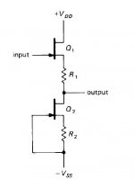
Could you comment on the attached drawing. It's an excerpt from "The Art Of Electronics" Horowitz and Hill. 2nd Edition. Pg 135
It talks about a source follower with source resistors R1=R2. Which guarantees Vo = Vi , if Q1 = Q2. This circuit has greater linearity when operated below IDSS. Compared to a circuit without source resistors.
Thanks,
Leo
Attachments
See post#1, Borbely's article Fig.15.
This is the circuit everyone knows, everyone uses in one form or another (Curl Follower, Pass B1, and my original DAO Follower, ....).
There are many detailed descriptions of this circuit on the inet. Please refer to the original B1 thread from Nelson.
http://www.diyaudio.com/forums/pass-labs/124889-b1-buffer-preamp-2.html#post1547019
http://www.analogzone.com/col_01302004.pdf
The purpose of my article was to show something different, and hopefully also somewhat better.
Patrick
Last edited:
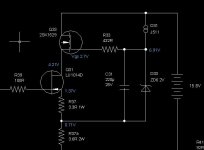
Someone asked me by PM for the low power version of the DAO with 100mA bias. I have to disappoint him because it was ages ago and I had so many versions that I did not document everything to a state that I can publish. But here is a slightly lower power version with 200mA bias, and only the top cell is shown. But it is easy to figure out how to copy and paste that to the bottom to form the current source I think.
And no, I don't have a TCS version that I can publish from my drawer. I probably have the calculation done somewhere in my archive, but I did not build one and am therefore not going to publish one. Perhaps one day when I retire and have more time, then I shall make them all available. In the meatime, please bear with me and build the high bias version that everyone who took the trouble seems to be extremely happy with.
Cheers,
Patrick
The original DAO follower circuit and its development history can be found here :
http://www.diyaudio.com/forums/pass-labs/95841-mosfet-follower-headphone-amplifier.html#post1130743
..
..
..
Attachments
Last edited:
I was thinking of building an M2 or a PPAv2 headamp (for those AKG 701's Santa will leave at my fireplace!) but this looks interesting..
It seems the Taylor version is..."taylored" (pun intended!) for the 701s.
Is there a PCB for us DIY newbies? Are there any parts that are hard to source?
It seems the Taylor version is..."taylored" (pun intended!) for the 701s.
Is there a PCB for us DIY newbies? Are there any parts that are hard to source?
Patrick, what do you think of lowering Pd by lowering supply voltage ?
+/-24V is too inefficient for just 2 or 3 volts of output signal. Cascoding MOSFETs won't feel well with lower Vds, so I thought to use BJTs instead (they don't mind). Cascoding devices don't have noticeable sound impact anyway, and with +/-12V we could keep original Id and still have half of Pd.
+/-24V is too inefficient for just 2 or 3 volts of output signal. Cascoding MOSFETs won't feel well with lower Vds, so I thought to use BJTs instead (they don't mind). Cascoding devices don't have noticeable sound impact anyway, and with +/-12V we could keep original Id and still have half of Pd.
Attachments
> Is there a PCB for us DIY newbies? Are there any parts that are hard to source?
Simple answer is no & no. There is a layout published that you can copy, or you just hard wire P2P, which is easy enough.
> with +/-12V we could keep original Id and still have half of Pd
If you argue that you only need 2V swing, then you hardly need more than 30mA current, which means that 200mA bias is a hell of a lot. I would still stick to 16V rail and 200mA bias, as I always want some voltage headroom. But by all means try it and let us know.
Patrick
....
If you argue that you only need 2V swing, then you hardly need more than 30mA current, which means that 200mA bias is a hell of a lot. I would still stick to 16V rail and 200mA bias, as I always want some voltage headroom. But by all means try it and let us know.
Patrick
Since this is single ended class A headamp I'd like some current headroom too - you are right about current for 50 Ohms headphones, but 16 Ohms devices are getting more and more popular.
That will be my next project, right now I'm busy with this circlotron (you'll remember the idea from F5 thread), and I have 1 channel working nicely:
Attachments
Hi Everyone,
I'm thinking about building the DAO follower headphone amp, maybe with the Taylor mod, and I have a couple of questions. (I'm not sure whether this is the right thread for them, really, since info about the DAO seems to be spread over a few threads.)
1. Somewhere I read the total draw is about 15W, I presume per channel. So a 60VA or 100VA toroidal trafo would be adequate, right? Toroidals down here in Brazil are pricy and hard to get - would there be much difference if I used a normal EI?
2. The photos of Steenoe's build show pretty big heatsinks, but if total draw is only 15W per channel it should be OK to use much smaller ones, right? Anyone have some kind of size estimate?
3. Has anyone put a crossfeed circuit in one of these? Not quite sure whether I want one, but I'd be interested to hear suggestions.
4. For a PSU circuit I'll probably use a version of Salas' regulator, and maybe put a B1-style buffer in to make the whole thing an integrated. Any thoughts?
Thanks for any help, and if all this is in the wrong thread let me know and I'll repost. (Or the mods can move it, I guess..)
Cheers
Nigel
1. The bias is about 200-250mA. If you use +/-20V rails, you will dissipate about 10W per channel.
So 20W for stereo, and 60VA will be fine. 100VA is plenty. But you will find little price difference between the two.
You can of course use normal EI, or even batteries.
If using EI, it is better to mount the transformer away from the amplifier to minimise magnetic disturbances.
2. You need a heat sink of say minimum 1W/°C.
3. Not me.
4. If you want to put a buffer upfront, you might as well add a proper line stage with gain instead.
But this depends on what headphone impedance you intend to drive with.
Hope this helps,
Patrick
- Home
- Amplifiers
- Pass Labs
- Some other Source Follower Configurations