generally, using current source instead of resistor
will measure better = lower THD
and lower 2nd and often less other lower order harmonics
Now, it has been told many times in different amplifiers
that resistor loaded can give a more pleasing sound (at resonable low 2nd, of course. Not like 1% !!!)
... even if the hi-fi factor in terms of Lowest THD
is not as high as for current sources.
For example Hugh Dean AKSA 55 uses resistor loading of input LTP + good old bootstrapping.
Instead of 2 CCS current sources in those places.
At least if I have been informed correctly.
Lineup
> is the Taylor CS possible with sureaMBs version of the Dao?
In theory yes. The circuit will work.
Read Nelson's article on Zen V9 regarding triode loadline, and you will understand why I cascode the way I did on the original DAO circuit, using MOSFETs.
No idea whether you get the same triode characteristics with a LU1014 Cascode and if so at what bias. Perhaps someone can Spice it and let us all know.
Patrick
PS I am not claiming that the LU1014 cascode is better or worse. I just don't know, not having tested it on breadboard.
Perhaps a few more remarks on the same topic.
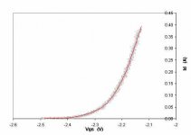
To use the LU1014 as the cascode device, you are dissipating something like 320mA x 20V in that device alone, which equals 6.4W. It will probably survive, but will run much hotter than the gain device itself. You might wish to reduce the rail voltages to say 12V.
In addition to that, the cascode device will have a different curve than the gain device.
The graph shown here is a LU1014 measured with 1R source resistor and 12V applied. This is likely to be how the cascode device behaves.
Patrick
Attachments
As you would expect, I have played with the idea of a simpler Cascode than enhancement mode mosfets as cascode.
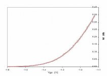
This is the curve of a LU1014 with a DN2540 depletion mosfet and 1R degeneration. The gate of the DN2540 is connected to the lower end of the 1R resistor.
The DN2540 has a TO-220 package, making heat dissipation a bit more convenient.
This is the curve of a LU1014 with a DN2540 depletion mosfet and 1R degeneration. The gate of the DN2540 is connected to the lower end of the 1R resistor.
The DN2540 has a TO-220 package, making heat dissipation a bit more convenient.
Attachments
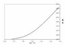
And finally, this is what I use myself -- a LU1014 with 2SK2013 cascode and 3R degeneration.
I am sure it is obvious which graph is more linear around 250mA.
Note that the X-axis is Vgs, i.e. the graphs are showing the characteristics of the gain device alone, and exclusing the degeneration resistor.
Patrick
I am sure it is obvious which graph is more linear around 250mA.
Note that the X-axis is Vgs, i.e. the graphs are showing the characteristics of the gain device alone, and exclusing the degeneration resistor.
Patrick
Attachments
Hi Patrick,
thanks a lot for the comparisons - very interesting und it's always fun to see some real numbers")
So you dropped your usual 2SK1529 for the 2SK2013? It's a pity these are hard to get. Do you remember maybe wether there was a significant improvement over the 2SK1529?
Have fun, Hannes
thanks a lot for the comparisons - very interesting und it's always fun to see some real numbers
So you dropped your usual 2SK1529 for the 2SK2013? It's a pity these are hard to get. Do you remember maybe wether there was a significant improvement over the 2SK1529?
Have fun, Hannes
one variant of this idea of yours, Tom2
has been used in Forssell All fet Op preamp
See here:
http://www.forsselltech.com/downloads/schematics/Class A JFet Opamp.PDF
Forssell is most know for something with
HIGHEST POSSIBLE hi-fi TURNTABLE arm movement = Air born travel
It is also very well worth to look into Forssell Products:
http://www.forsselltech.com/products.shtml
Rack Mounted Products
JMP-6 Six Channel Mic Preamp
SMP-2 Discrete JFET Mic Preamp New
FetCode Tube Mic Preamp
CS-1 Channel Strip
NSEQ-F Upgrade PCB
Class A Discrete JFET Modules
JFET-992 Discrete Opamp
JFET-993 Discrete Opamp
DLR-1 Differential Line Receiver
JMP-1 Transformerless Mic Preamp
Unity Gain Buffer Module
For a DC bias of 250mA, it is an overkill to use 2SK1529. That is the only reason why I used 2SK2013. But you can use 2SK1529 just as well, maybe slightly increase the source resistor to 3R6.
As to the circuit proposed by Tom2, you have not solved the problem I mentioned of the complementary follower -- namely the high input capacitance. And I do not see the advantage of using extra 2 FETs and 2 resistors, as compared to Fig. 16B of Borbely's article.
Patrick
As to the circuit proposed by Tom2, you have not solved the problem I mentioned of the complementary follower -- namely the high input capacitance. And I do not see the advantage of using extra 2 FETs and 2 resistors, as compared to Fig. 16B of Borbely's article.
Patrick
But the Toshibas need a different gate voltage to the IRFPs.
Don't worry, Sir. I know
Have fun, Hannes
Taylor'ed DAO
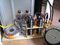
I have built one more DAO, this time with the Taylor mod, and it sounds great indeed. The Taylor mod added a bit more transparancy, which is now approaching electrostatic territory.
The best I heard yet with dynamic headphones.
The difference from the original DAO is subtle, which is not surprising since it is allready a very good headphoneamp. The one with the Taylor is just that tad better though, so it is absolutely worthwhile to implement the Taylor mod.
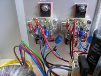
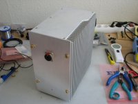
Overall it sounds very organic and natural with clear clean highs and deep firm low's. No sign of listening fatigue at any volume level, even for long listening periods. It also has the music in a firm grip at all times, even at high levels and massive music it never gets muddy in the sound. I can easily live with this headphoneamp Attached is a pic of the test setup, with the Taylor hanging in the lower right corner of each board. The supply is a shared 160VA 2x18V donut, with 40.000uF and 1,8mH in a CLC config for each channel. It is dead quiet without signal.
Thanks a lot for sharing, Patrick.
I have built one more DAO, this time with the Taylor mod, and it sounds great indeed. The Taylor mod added a bit more transparancy, which is now approaching electrostatic territory.
The best I heard yet with dynamic headphones.
The difference from the original DAO is subtle, which is not surprising since it is allready a very good headphoneamp. The one with the Taylor is just that tad better though, so it is absolutely worthwhile to implement the Taylor mod.
Overall it sounds very organic and natural with clear clean highs and deep firm low's. No sign of listening fatigue at any volume level, even for long listening periods. It also has the music in a firm grip at all times, even at high levels and massive music it never gets muddy in the sound. I can easily live with this headphoneamp
Attached is a pic of the test setup, with the Taylor hanging in the lower right corner of each board. The supply is a shared 160VA 2x18V donut, with 40.000uF and 1,8mH in a CLC config for each channel. It is dead quiet without signal.Thanks a lot for sharing, Patrick.
Attachments
- Home
- Amplifiers
- Pass Labs
- Some other Source Follower Configurations