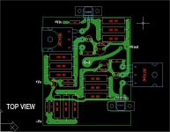
> Just for giggles. this is how the DAO V1. looks like.
Hey this looks great.
The Taylor mod will make more difference if you have a low impedance headphone, such as the AKG 701 or Grado's.
If you are prepared to go the next step (see my PM), I shall do a new PCB for that and publish it here.
One (and the same) happy customer once more. I hope some of you will take the plunge and try this circuit (with the new PCB in due course).
")
Patrick
Hey this looks great.
The Taylor mod will make more difference if you have a low impedance headphone, such as the AKG 701 or Grado's.
If you are prepared to go the next step (see my PM), I shall do a new PCB for that and publish it here.
One (and the same) happy customer once more. I hope some of you will take the plunge and try this circuit (with the new PCB in due course).
Patrick
Hannes,
I cannot promise to finish the new PCB layout this week, but if you want to have a go, you can take the basic DAO layout, replace all 3W resistors with 3x PRP 1W audio resistor in parallel. For the source resistor, use 3x 12R; for the Taylor R2, R3, use 2x15R // 1x 12R.
You might also want a larger footprint for the cap across the Cascode Zener. If cost is no issue, then Blackgate standard 100uF 16V. Otherwise Panasonic FC in parallel with a 100n film cap. Or try Os-Con on its own. I emphasis try. Look at the 100kHz square wave reponse under load.
Patrick
Dao Tcs-x
I mentioned in Post #19 that the DAO Follower with Taylor Current Source (TCS) has 20dB more 2nd than without, but has also 20dB lower distortion from 3rd harmonics onwards.
Of course one can use two DAO TCS in balanced mode, which will easily reduce even harmonics by a factor of 10 if the devices are well matched. But that is a no-brainer.
So this one is for Hannes -- why not cross-couple the 2 TCSs in balanced mode ?
Now we have DAO with TCS-X !!
Cheers,
Patrick
Attachments

DAO TCS as Power Amp ?
To use the circuit as power amp, you need to reduce the source resistor of the LU1014 to 0.67R and set the cascode the same way as Zen V9. 3x LU1014 in parallel will require 4A bias and have a output impedance of about 0.3R, which is sort of high, even when combined with the Taylor Current Source.
There is no simple way to reduce this in a follower circuit. That is why I did not post such a circuit to drive speakers.
Patrick
>Of course one can use two DAO TCS in balanced mode, which will easily reduce even harmonics by a factor of 10 if the devices are well matched. But that is a no-brainer.
Just curious could the negative input be grounded to get balanced outputs or does it need to be driven with a balanced source?
Sean
Just curious could the negative input be grounded to get balanced outputs or does it need to be driven with a balanced source?
Sean
> To use the circuit as power amp, you need to reduce the source resistor of the LU1014 to 0.67R and set the cascode the same way as Zen V9. 3x LU1014 in parallel will require 4A bias and have a output impedance of about 0.3R, which is sort of high, even when combined with the Taylor Current Source. There is no simple way to reduce this in a follower circuit. That is why I did not post such a circuit to drive speakers.
A member of the forum was discussing with me off line about using the DAO TCS-X as power amp :
http://www.diyaudio.com/forums/showthread.php?postid=1613058#post1613058
The comment about the source resistor still applies. But with the Taylor current source, the output impedance will be reduced by half to around 0.15R. This is not far off that of the F4 circuit, as the LU1014 has somewhat higher transconductance at 1.3A than IRFP240. The values of R1,2,3,4 would need some adjustment, depending on how many FETs in parallel. I am out of town right now, so this will have to wait a couple of weeks. But judging from Steen's results and my simulations, this will give the F4 a run for its money, especially the X'ed balanced version (with 12 LU1014s and 12 IRFP240 as cascode).
Patrick
Oh Dear!
Patrick, or somebody - could you help to tell me how to open the zipped ccts on post 4, 77, and 48.
The discussion is a bit vague without the Ccts!
Not very "clued-up" about computers, I'm afraid - I end up getting told to copy it into temporary files, etc but just won't open. Frustrating!!
Patrick, or somebody - could you help to tell me how to open the zipped ccts on post 4, 77, and 48.
The discussion is a bit vague without the Ccts!
Not very "clued-up" about computers, I'm afraid - I end up getting told to copy it into temporary files, etc but just won't open. Frustrating!!
I don't understand your problem.
Don't you have winzip ?
If not I am sure you can get a free download somewhere.
After you unzip, it is actually a Word document.
I have not heard anyone else having problem except for those who use Linux.
Maybe someone else knows better.
Patrick
Don't you have winzip ?
If not I am sure you can get a free download somewhere.
After you unzip, it is actually a Word document.
I have not heard anyone else having problem except for those who use Linux.
Maybe someone else knows better.
Patrick
- Home
- Amplifiers
- Pass Labs
- Some other Source Follower Configurations