I know that PCB is a hurdle for a lot of people.
That is why we are doing this.
But we need to finish a few other things first before we have time to build this proto.
Patrick
Great work
")
I think there is no problem about the time. May I ask if u can share the schematics as well, or it is to early?
Thank you
I tried an LTSpice simulation based on the schematic provided by Patrick in post #4, but the I cannot get the offset voltage to be near zero with reasonable values of R1 and/or R2., and the distortion results are much worse than shown in this thread. I suspect that the spice models I am using are inappropriate. Can anyone point me to spice models that work for this circuit?
My simulations were not done with LT SPice, but real device measurements then calculated in Excel.
You probably need to trim the values of the 2SJ103 model until you get Idss of 8mA, but even then it is still not reality.
There is no easy way other than to build, I am afraid.
Patrick
You probably need to trim the values of the 2SJ103 model until you get Idss of 8mA, but even then it is still not reality.
There is no easy way other than to build, I am afraid.
Patrick
Is DAO follower with Taylor a Class-A Quasi-Comp topology?
What distinguishes the circuit of post #4 from a Quasi-Complementary circuit? It has all of the attributes:
. Upper output FET operates in common-drain (ie. source follower) mode
. Lower output FET operates in common-source mode
. The combination of Q1 and Q3 forms a phase-splitter.
What distinguishes the circuit of post #4 from a Quasi-Complementary circuit? It has all of the attributes:
. Upper output FET operates in common-drain (ie. source follower) mode
. Lower output FET operates in common-source mode
. The combination of Q1 and Q3 forms a phase-splitter.
The Taylor current source is a form of quasi-pushpull, except that the main driving device (the upper FET) is driven directly by the signal, and the current source is modulated by the current of the top device sensed by Q3. In a quasu complementary, both devices are driven by the phase splitter.
For more details of the working principle, please google "tubecad taylor current source".
Patrick
For more details of the working principle, please google "tubecad taylor current source".
Patrick
No, let me finish off the F5X first.
No time right now, next to full time job, business travel, looking after elderly parents, family, ....
When in 5 years time, I can afford to retire to do Audio (for fun) full time, then there will be more progress at an acceptable pace.
Sorry,
Patrick
No time right now, next to full time job, business travel, looking after elderly parents, family, ....
When in 5 years time, I can afford to retire to do Audio (for fun) full time, then there will be more progress at an acceptable pace.
Sorry,
Patrick
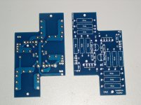
Mark is preparing to build the first proto.
Patrick
cool, are you still sticking to the same current sources? those CRDs are cool, but not that easy to find and expensive
- Home
- Amplifiers
- Pass Labs
- Some other Source Follower Configurations