Thanks Uli . 
Very nice work indeed .
I made some bias calcs and the whole thing seems to run fine on the paper .
It seems 2 mA running through each led . These have to be selected , in a low current batch to have the desired value of 1,65 V drop at 2 mA . Seems hard to find practicaly ! There is the same problem for the Alephono")
Seems 4,95 mA through each half of the 2sk 369/389 . So I think having some GR/BL types will do it .
I understood that the 2 BC 559 of the top left and right hold the 2 branch following down , i.e. the 2sk and the output section cascoded . So in allowing more bias it is important not to go upper than 400mW for those bipolars

And the output followers . I will use some 610/9610 for the preamp version . I wish not to include those in the global feedback , so I will go for a healthy bias for those .
1) is 40 mA enough for a linestage ?
2) to reach the 40mA , is a 2k2 trimmer in place of R12/14/11/13 enough ? multiturn of course .
3) 610/9610 mounted on same heatsink ? Necessary ?
4) VGS 610/9610 matched at desired current?
5)I will use capacitor at the output as it is really necessary to protect XA amp in case of failure
To get more bias at the outputs , why not use the BC 327/337 ? I seem to remember they tand higher currents .
Do you recommand to leave R 21/22 in the circuit ? Why ?
I will use external network for the inputs as you said , with a 10 K series and 100 parallel to gnd . And input caps ...
so in that case , with the output followers in place , the gain is load independant and would be the ratio of R 17 / R input ( 10k) ? Same for R18 / 10k ?
220/ 10 = 22 , tension gain or 26.84 dB ?
Really interesting !!!!
Regards
Anael
Very nice work indeed .
I made some bias calcs and the whole thing seems to run fine on the paper .
It seems 2 mA running through each led . These have to be selected , in a low current batch to have the desired value of 1,65 V drop at 2 mA . Seems hard to find practicaly ! There is the same problem for the Alephono
Seems 4,95 mA through each half of the 2sk 369/389 . So I think having some GR/BL types will do it .
I understood that the 2 BC 559 of the top left and right hold the 2 branch following down , i.e. the 2sk and the output section cascoded . So in allowing more bias it is important not to go upper than 400mW for those bipolars
And the output followers . I will use some 610/9610 for the preamp version . I wish not to include those in the global feedback , so I will go for a healthy bias for those .
1) is 40 mA enough for a linestage ?
2) to reach the 40mA , is a 2k2 trimmer in place of R12/14/11/13 enough ? multiturn of course .
3) 610/9610 mounted on same heatsink ? Necessary ?
4) VGS 610/9610 matched at desired current?
5)I will use capacitor at the output
as it is really necessary to protect XA amp in case of failure To get more bias at the outputs , why not use the BC 327/337 ? I seem to remember they tand higher currents .
Do you recommand to leave R 21/22 in the circuit ? Why ?
I will use external network for the inputs as you said , with a 10 K series and 100 parallel to gnd . And input caps ...
so in that case , with the output followers in place , the gain is load independant and would be the ratio of R 17 / R input ( 10k) ? Same for R18 / 10k ?
220/ 10 = 22 , tension gain or 26.84 dB ?
Really interesting !!!!
Regards
Anael
Hi Uli ,
Got it work !!!
I had those measurements
V rails + / - 25 V
Measure on
R 2 1 V
R 4 14,2 V
R 9 1,072 V
R 10 1,077 V
Those emiters resistors are 200 ohms 1%
I let it go for 1 hour , everything was perfect I guess.
Except ...
I wanted to run measurements again .
Accidentally I did a short . I wanted to measure accurately voltage on R2 , and my probe did a short between point of R 2 going to emiter and ground ( the layout is quite small . Ouups...
Now it doesn't work anymore , I am not happy
I think doing that , logically T3 didn't appreciate to see his emiter go to 0V instead of -24V
The 2 leds are not on , what a mistake I have done
Nothing smokes or overheat
Now it is question to change T3
I think everything else is fine ?
I have to check everything .
The problem is the layout is so small , it will take some time to change T3
Do you think I need to change anything else ? Zeners ? Leds ?
Measuring at the - drive + drive out points , I have now 1.8V
When it was OK , I had a correct value of 8,7 V or so , I didn't adjust the upper current sources yet
Please Uli your advice on my breakdown problems .
Best regards
Anael
PS please don't tell me I have to change all bipolars jfets leds zeners
It took me hours of carefull soldering and checks for no shorts
!!!!!!!!!!!!!!!!!!!!!!
Well !!! I repaired it !!! It works again !!!
In fact I checked everything . Zeners first .
Using the diode test of the multimeter ( that helps a lot ! ) I had
Zeners showing 0,7 in one way/ other way nothing . Clearly they were OK .
Verified T4-T10 using same method between base and emiter . Same for T5-T11. OK .
T3 had gone . i was sad
R.I.P. I put another one in .
The red leds had gone too . Changed them .
Plugged it again ...and the leds light !!!
I have to carefully run some measurements again ( to protect hours spent on that 4*5 cm PCB
The 2sk389 clearly survived . However , I don't know if good again to pass sound .
I will construct now input network and output followers on an experiment board . And see If I have good current passing through the Mosfets .
Afterwards ... why not listen to it ? ?
Regards
Anael
In fact I checked everything . Zeners first .
Using the diode test of the multimeter ( that helps a lot ! ) I had
Zeners showing 0,7 in one way/ other way nothing . Clearly they were OK .
Verified T4-T10 using same method between base and emiter . Same for T5-T11. OK .
T3 had gone . i was sad
R.I.P. I put another one in .
The red leds had gone too . Changed them .
Plugged it again ...and the leds light !!!
I have to carefully run some measurements again ( to protect hours spent on that 4*5 cm PCB
The 2sk389 clearly survived . However , I don't know if good again to pass sound .
I will construct now input network and output followers on an experiment board . And see If I have good current passing through the Mosfets .
Afterwards ... why not listen to it
? ?Regards
Anael
Hi Uli ,
Don't know if you are on the threads or in holidays....
I seem to make the X -modul work ,
but strange things .
The DC offset is always wandering around . I talk about DC offset per s.e. , i.e. absolute DC.
Regularly , it goes as high as 5V DC , then goes down to 0 and starts again .
With a different tuning of the upper trimmers, I have a good control of the DC , but it always move.
Differential DC is much more stable , but it's a hair trigger to get things stable
I grounded inputs to adjust eveything . Seems it doesn't help .
It is true I have no output load to the module .
Maybe I should try with some 10 k to ground at the outputs as a load .
I will try adding input network.Maybe without , gain is too high and causes instability in all parameters .
Please Uli !!!!
Where are you ???
Hi to everybody !
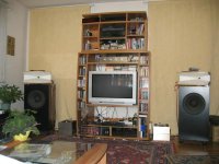
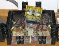
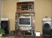
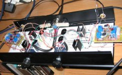
This is my attempt to use the X modul as a real life preamp .
I would like to thank Uli very much for his wonderful thoughts and help in making this sound damn good ... crazy but it works ! And fine .
The 4 * magical resistors are now 22k1
Yes the offset drifts but within a safety marge ( +/- 2V )
The output followers ( basic structure of X amps ) are 610/9610 i pure class A , 40mA bias at 25 V rails .
Sound is .....


Here is the pic :
This is my attempt to use the X modul as a real life preamp .
I would like to thank Uli very much for his wonderful thoughts and help in making this sound damn good ... crazy but it works ! And fine .
The 4 * magical resistors are now 22k1
Yes the offset drifts but within a safety marge ( +/- 2V )
The output followers ( basic structure of X amps ) are 610/9610 i pure class A , 40mA bias at 25 V rails .
Sound is .....
Here is the pic :

I might build the whole circuit again, as I found some 2SK363 NOS I could use for the diff. pair. I figured out that in my configuration, I would only need X4 gain at max for the pre ... max scale would be to clip the Aleph 4 amps
Furthermore, I need to re do the output followers but yes I will try single-ended. a 2SK389V could be a nice candidate for the strictly followers at high current
But, to match the 2SK363, only IDSS, or also V Gate -Emiter at the desired current ?
EDIT: last sample I built had the best bass I ever heard - tight, controlled and extended
Cheers,
nAr - bringing the old threads to life
Last edited:
- Status
- This old topic is closed. If you want to reopen this topic, contact a moderator using the "Report Post" button.
- Home
- Amplifiers
- Pass Labs
- X-Modul